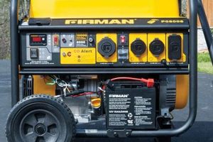
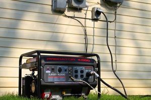
A diagram illustrating the electrical connections and components within a compact, mobile power source clarifies how the generator’s internal systems interact to produce and regulate electricity. This visual representation typically details the pathways of current flow, the arrangement of essential elements like the alternator, voltage regulator, and control panel, and the connections for output receptacles. A practical example might depict the flow of power from the engine to the alternator, then through the voltage regulator and finally to the outlets.
Understanding such a diagram is crucial for safe operation, troubleshooting, and maintenance. It allows users to diagnose potential issues, perform repairs, and ensure the generator’s longevity. Historically, these diagrams have evolved alongside advancements in generator technology, reflecting improvements in efficiency, safety features, and electronic control systems. Their clear presentation of complex systems empowers users with the knowledge needed for safe and effective power generation.
This foundation in the visual representation of these power sources prepares for a deeper exploration into topics such as safety protocols, common wiring configurations, troubleshooting techniques, and the selection of appropriate components for specific applications.
Safety and Efficiency Tips for Generator Wiring
Careful consideration of wiring practices is paramount for safe and reliable generator operation. The following tips offer guidance for ensuring optimal performance and mitigating potential hazards.
Tip 1: Consult Manufacturer Documentation: Always refer to the specific diagrams and instructions provided by the manufacturer. Variations in design and components exist among different models.
Tip 2: Use Appropriately Sized Wiring: Wire gauge should be selected based on the amperage requirements of the connected loads and the length of the wiring run. Undersized wiring can overheat, creating a fire hazard.
Tip 3: Grounding is Essential: Proper grounding is crucial for preventing electrical shock. Ensure the generator’s frame and grounding wire are correctly connected.
Tip 4: Secure Connections: Loose connections can cause arcing and overheating. All wire connections should be tight and secure using appropriate connectors.
Tip 5: Weatherproof Connections: For outdoor use, connections should be protected from the elements using weatherproof enclosures and sealant.
Tip 6: Overcurrent Protection: Employ circuit breakers or fuses to protect the generator and connected equipment from damage due to excessive current flow. Select devices with appropriate ratings.
Tip 7: Regular Inspection: Periodically inspect wiring for signs of damage, wear, or loose connections. Address any issues promptly.
Adherence to these practices contributes significantly to the safe and efficient operation of a generator, safeguarding both equipment and individuals.
These practical tips provide a solid foundation for understanding the importance of proper wiring. Further sections will delve into specific applications and more advanced troubleshooting techniques.
1. Safety
Safety is paramount when dealing with portable generator wiring schematics. A clear understanding of the schematic is fundamental to safe generator operation, maintenance, and troubleshooting. The schematic provides a roadmap of the electrical system, enabling users to identify potential hazards and implement appropriate safety measures. Failure to comprehend the schematic can lead to improper wiring, resulting in risks such as electrocution, fire, and equipment damage. For example, incorrectly connecting the grounding wire, as detailed in the schematic, can create a shock hazard. Understanding the schematic’s representation of overcurrent protection devices, like fuses and circuit breakers, allows for their correct implementation, preventing potential fires caused by excessive current flow.
Practical applications of this understanding are numerous. During installation, the schematic guides correct wiring practices, minimizing risks from the outset. When troubleshooting malfunctions, the schematic allows for safe and systematic diagnosis of electrical issues. Maintenance tasks, such as replacing components or inspecting wiring, are performed more safely and effectively with a clear understanding of the generator’s electrical layout. Furthermore, the schematic aids in selecting appropriately sized wiring and protective devices, further enhancing operational safety. Comprehending the interplay of components within the schematic empowers users to anticipate and mitigate potential safety hazards.
In conclusion, a comprehensive understanding of a portable generator wiring schematic is not merely a technical skill but a critical safety imperative. It forms the foundation for safe installation, operation, maintenance, and troubleshooting, protecting both individuals and equipment. Challenges in interpreting the schematic can be overcome through careful study and consultation with qualified electricians, ensuring the safe and effective utilization of portable generators. This knowledge ultimately contributes to minimizing the risks associated with electricity generation and promoting a secure operating environment.
2. Components
A portable generator wiring schematic serves as a blueprint, illustrating the interconnection of various components essential for power generation. These components, including the engine, alternator, voltage regulator, control panel, and various protective devices, work in concert to produce and regulate electrical output. The schematic details the precise arrangement and connection of these elements, crucial for understanding the generator’s operation. For example, the schematic depicts the alternator’s connection to the engine, demonstrating how mechanical energy converts into electrical power. Similarly, the connection between the voltage regulator and the alternator reveals the mechanism for maintaining stable output voltage. Furthermore, the schematic illustrates the integration of safety components such as circuit breakers and fuses, crucial for preventing overloads and short circuits.
Understanding the role and interconnection of each component within the schematic is essential for troubleshooting and maintenance. A malfunctioning voltage regulator, identifiable through its schematic representation, might explain unstable output voltage. Similarly, the schematic guides the replacement of a faulty circuit breaker, ensuring continued safe operation. Practical applications extend to system upgrades, where the schematic informs the integration of additional components like transfer switches or remote control panels. This comprehensive visualization of the system’s components facilitates informed decision-making regarding maintenance, repairs, and system expansion.
In summary, the schematic provides a critical visual representation of the generator’s components and their interrelationships. This understanding is fundamental for effective troubleshooting, maintenance, and system modification. Challenges in interpreting component symbols within the schematic can be addressed through consultation with manufacturer documentation or experienced technicians. Ultimately, a thorough grasp of component interaction, as depicted in the schematic, is essential for safe, efficient, and reliable generator operation.
3. Connections
A portable generator wiring schematic provides a visual representation of the intricate network of connections within the generator. These connections, depicted through lines and symbols, represent the pathways for electrical current flow between various components. Understanding these connections is paramount for safe operation, effective troubleshooting, and proper maintenance. The integrity and security of these connections directly impact the generator’s performance and longevity.
- Wiring Integrity:
Wiring integrity refers to the quality and condition of the wires and connectors used within the generator’s electrical system. The schematic details the specific gauge and type of wire required for each connection, crucial for ensuring safe and efficient operation. Damaged or corroded wires, identifiable through visual inspection guided by the schematic, can lead to performance issues or safety hazards. For example, a frayed wire connected to the alternator, as depicted in the schematic, could lead to power loss or even a fire hazard. Maintaining wiring integrity is paramount for reliable and safe generator performance.
- Connector Types:
The schematic specifies the appropriate type of connector for each connection point. These may include crimp connectors, spade connectors, ring terminals, or other specialized connectors. Using incorrect connectors can compromise the connection’s integrity, leading to increased resistance, heat buildup, and potential failure. The schematic aids in selecting the correct connector type, ensuring secure and reliable connections throughout the generator’s electrical system. For example, using a spade connector where a ring terminal is specified, as indicated in the schematic, could create a loose connection and potential safety hazard.
- Grounding System:
The schematic highlights the crucial grounding system connections. It illustrates the path from the generator’s frame to the grounding electrode, essential for preventing electrical shock. Understanding this pathway, as depicted in the schematic, allows for proper grounding system installation and verification. A compromised grounding connection, identifiable through the schematic, poses a significant safety risk. Regular inspection and maintenance of the grounding system, guided by the schematic, are essential for ensuring operator safety.
- Output Connections:
The schematic details the connections for the generator’s output receptacles. It clarifies the wiring configuration for different voltage and amperage outputs. This information is essential for safely connecting appliances and equipment to the generator. Misinterpreting the output connections, as depicted in the schematic, can lead to equipment damage or overloading the generator. Properly connecting loads according to the schematic ensures safe and efficient power distribution.
The intricate network of connections within a portable generator, as detailed in its wiring schematic, forms the backbone of its operation. Each connection plays a vital role in ensuring safe and efficient power generation. A comprehensive understanding of these connections, their types, and their importance is fundamental for proper installation, maintenance, and troubleshooting. This knowledge empowers users to operate their generators safely and effectively, maximizing their lifespan and minimizing potential hazards. Further exploration of specific connection points and their related safety considerations will provide a more granular understanding of the generators electrical system.
4. Current Flow
A portable generator wiring schematic maps the intended pathways of electrical current flow. Understanding this flow is crucial for safe operation, effective troubleshooting, and system modification. The schematic illustrates how current travels from the power source (typically the alternator) through various components, such as the voltage regulator, control panel, and ultimately to the output receptacles. This visual representation allows users to trace the circuit from source to load, clarifying how different components interact and contribute to the overall power generation process. For instance, the schematic depicts the flow of current through protective devices like circuit breakers and fuses, highlighting their role in preventing overloads and short circuits. A practical example is tracing the current path from the alternator through a circuit breaker to a specific outlet, illuminating how that outlet receives power and how it is protected.
Analyzing current flow within the schematic is essential for diagnosing and resolving electrical issues. If an outlet lacks power, the schematic guides the user to trace the current path, identifying potential points of failure along the way. A break in the wire, a faulty connection, or a tripped circuit breaker, all visible within the schematic context, can be identified as potential culprits. Similarly, when adding new components or modifying the system, understanding current flow is essential for ensuring proper integration and avoiding unintended consequences. Incorrectly connecting a new outlet, for instance, could disrupt the intended current flow, leading to overloads or malfunctions in other parts of the system. Furthermore, understanding current flow enables informed decisions regarding wire sizing and protective device selection, ensuring system safety and efficiency.
Comprehending current flow, as depicted within a portable generator wiring schematic, is fundamental for safe and effective generator operation. This knowledge facilitates accurate troubleshooting, informed system modifications, and proper component selection. Challenges in interpreting current flow within complex schematics can be addressed through consultation with manufacturer documentation or qualified electricians. This understanding ultimately contributes to optimizing generator performance, enhancing safety, and maximizing the lifespan of the equipment. It provides a critical foundation for navigating the intricacies of portable power generation systems.
5. Wiring Gauge
Wiring gauge is a critical element within a portable generator wiring schematic, directly impacting the generator’s safe and efficient operation. The schematic specifies the appropriate American Wire Gauge (AWG) for each segment of the wiring system. This specification, based on the anticipated amperage load and the length of the wire run, ensures the wiring can safely handle the electrical current without overheating. Using an inadequate gauge, thinner than specified, presents a significant fire hazard due to excessive heat generation. Conversely, using an unnecessarily large gauge, thicker than required, adds cost and can make connections cumbersome. The schematic, therefore, serves as the definitive guide for selecting the correct wiring gauge, balancing safety and efficiency.
Consider a scenario where a generator powers several high-wattage appliances. The schematic might specify a 10 AWG wire for the connection between the generator and the main distribution panel, given the high current demand. However, for individual connections to lower-wattage devices, the schematic might specify a 14 AWG wire, reflecting the reduced current requirements. Ignoring these specifications and using a smaller gauge for the high-wattage circuit could lead to dangerous overheating. Conversely, using a larger gauge than necessary for the low-wattage connections adds unnecessary cost and complexity. Practical applications extend to extension cord selection, where the schematic’s guidance on wire gauge ensures safe operation and prevents voltage drops that can damage sensitive electronics. Furthermore, understanding the relationship between wire gauge, amperage, and wire length, as depicted in the schematic, allows for informed decisions about cable management and placement, optimizing generator performance and longevity.
Accurate wire gauge selection, as specified within the portable generator wiring schematic, is fundamental for ensuring safety and efficiency. This understanding prevents fire hazards associated with undersized wiring and avoids unnecessary costs associated with oversized wiring. Challenges in determining the correct wire gauge can be addressed by consulting ampacity charts and seeking guidance from qualified electricians. Adhering to the schematic’s wire gauge specifications ensures reliable generator operation, minimizes risks, and maximizes the lifespan of the electrical system. This attention to detail underscores the importance of treating the schematic not merely as a diagram, but as a critical safety and performance document.
6. Grounding
Grounding within a portable generator’s electrical system, as depicted in its wiring schematic, is a non-negotiable safety measure. The schematic illustrates the crucial connection between the generator’s frame and a grounding electrode, typically a rod driven into the earth or a connection to a building’s grounding system. This connection provides a low-resistance path for fault currents to flow into the earth, preventing dangerous voltage buildup on the generator’s metallic parts. Without proper grounding, a fault condition could energize the generator’s frame, posing a lethal shock hazard to anyone coming into contact with it. The schematic’s depiction of the grounding system allows for proper installation and verification of this critical safety feature. A practical example is a ground fault caused by damaged insulation within the generator. With proper grounding, the fault current flows safely to earth, tripping a circuit breaker and de-energizing the faulty circuit. Without grounding, the generator’s frame could become energized, presenting a severe shock hazard.
Further analysis of the grounding system within the schematic reveals its importance in protecting sensitive electronic equipment. Grounding provides a stable reference point for voltage, minimizing the risk of damage from voltage spikes or surges. Moreover, the grounding system plays a crucial role in reducing electrical noise and interference, which can disrupt the operation of electronic devices connected to the generator. Consider a scenario where a generator powers a computer during a power outage. Proper grounding, as depicted in the schematic, protects the computer from damage caused by voltage fluctuations and minimizes disruptions due to electrical noise. Practical applications extend to construction sites, where proper generator grounding is essential for worker safety and equipment protection. The schematic serves as a guide for ensuring compliance with safety regulations and mitigating potential hazards in challenging environments.
In conclusion, the grounding system, as meticulously detailed in the portable generator wiring schematic, is fundamental for operator safety and equipment protection. It establishes a low-resistance path for fault currents, preventing potentially lethal electrical shocks. Furthermore, it safeguards sensitive electronic equipment from voltage fluctuations and electrical noise. Challenges in implementing proper grounding, such as ensuring a low-resistance connection to earth, can be addressed through consultation with electrical codes and qualified electricians. A comprehensive understanding and meticulous adherence to the schematic’s grounding instructions are paramount for ensuring a safe and reliable power generation environment. This understanding transforms the schematic from a mere diagram into a critical document safeguarding both individuals and equipment.
Frequently Asked Questions about Generator Wiring Schematics
This section addresses common inquiries regarding the interpretation and utilization of portable generator wiring diagrams.
Question 1: Where can one locate a wiring diagram for a specific generator model?
Manufacturer documentation, typically included with the generator or available online, provides model-specific wiring diagrams. These diagrams offer precise details regarding the generator’s electrical system.
Question 2: What do the various symbols and lines represent within a wiring schematic?
Standardized symbols represent electrical components such as resistors, capacitors, switches, and fuses. Lines depict the wires connecting these components, illustrating the pathways of current flow. Consulting a symbol legend, often included with the schematic, clarifies the meaning of each element.
Question 3: How does one interpret the wire gauge specifications within a schematic?
Wire gauge specifications, typically denoted by AWG numbers, dictate the appropriate wire thickness for various segments of the wiring system. Lower AWG numbers indicate thicker wires capable of carrying higher currents. Adhering to these specifications is crucial for preventing overheating and ensuring safe operation.
Question 4: What safety precautions should be observed when working with generator wiring?
De-energizing the generator before performing any wiring work is paramount. This involves disconnecting the spark plug wire and removing any external power sources. Using insulated tools and wearing appropriate safety gear, such as gloves and eye protection, further mitigates potential hazards.
Question 5: How can one determine the appropriate wire type for generator wiring?
Specific wire types, such as stranded copper wire with appropriate insulation, are typically recommended for generator wiring. Consulting the manufacturer’s recommendations and relevant electrical codes ensures compatibility and safe operation. Factors such as temperature rating and resistance to abrasion should also be considered.
Question 6: What steps should be taken if the wiring schematic appears damaged or illegible?
Contacting the manufacturer directly or consulting authorized service centers provides access to replacement schematics. Attempting to interpret a damaged or illegible schematic can lead to incorrect wiring and potentially dangerous outcomes.
Understanding and correctly interpreting a wiring schematic is fundamental for safe and effective generator operation. Careful consideration of these frequently asked questions enhances comprehension and promotes responsible generator usage.
The next section provides further guidance on troubleshooting common generator wiring issues.
Understanding Portable Generator Wiring Schematics
Careful examination of portable generator wiring schematics reveals their crucial role in safe and efficient power generation. These diagrams provide invaluable insights into the intricate network of components, connections, and current pathways within these complex systems. From the alternator to the output receptacles, understanding each element’s function and interrelationship is paramount. Proper wire gauge selection, dictated by the schematic, ensures safe current carrying capacity, while meticulous attention to grounding safeguards against electrical hazards. Comprehending these interconnected elements empowers users to operate, maintain, and troubleshoot their generators effectively.
Mastery of these schematics represents more than just technical proficiency; it embodies a commitment to responsible generator usage. This knowledge minimizes risks, optimizes performance, and extends equipment lifespan. Continued emphasis on schematic comprehension and adherence to safety guidelines will ensure reliable portable power for future needs. Diligence in these areas contributes significantly to a secure and efficient power landscape.

