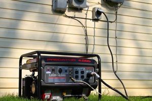
A schematic representation illustrates the electrical connections and components within a small, movable power source designed for household electricity. This visual guide typically depicts the generator’s internal windings, outlets, control panel elements, and safety features like circuit breakers and grounding connections. An example might show how the alternator’s output connects to the voltage regulator, then to the various outlets, illustrating the flow of electrical current.
Such a representation is critical for safe operation, maintenance, and troubleshooting. Understanding the electrical pathways allows users to connect appliances correctly, avoiding damage from overloads or improper grounding. It also aids in diagnosing faults, enabling efficient repairs by pinpointing the source of issues. Historically, these diagrams were primarily used by technicians. However, with the increasing prevalence of these power sources in homes and businesses, readily available graphical representations have become vital for wider user understanding and safe operation.
This foundational understanding paves the way for exploring topics such as generator sizing, load balancing, proper grounding techniques, safety protocols, and troubleshooting common issues. Further exploration of these topics will equip users with the knowledge necessary for safe and effective power generation.
Safety and Operational Tips
Careful consideration of the following points ensures safe and effective generator operation and maintenance.
Tip 1: Consult the Manufacturer’s Documentation: Always refer to the specific diagram provided with the unit. Variations exist between models, and adhering to manufacturer specifications is paramount for safety and warranty compliance.
Tip 2: Grounding is Essential: Proper grounding prevents electrical shocks and protects equipment. The diagram illustrates the grounding system, highlighting the importance of a secure earth connection.
Tip 3: Understand Capacity Limits: Exceeding the rated wattage can damage both the generator and connected appliances. The diagram clarifies the power output available at each outlet.
Tip 4: Safe Connections are Crucial: Use appropriately sized wiring and connectors to prevent overheating and fire hazards. The diagram specifies wire gauges and connection points.
Tip 5: Regular Maintenance is Key: Scheduled inspections and maintenance, including oil changes and air filter cleaning, ensure optimal performance and longevity. Consult the provided documentation alongside the diagram for specific maintenance requirements.
Tip 6: Beware of Backfeeding: Never connect a generator directly to household wiring without a properly installed transfer switch. This dangerous practice can energize downed power lines, posing a risk to utility workers.
Tip 7: Operate in a Well-Ventilated Area: Generators produce carbon monoxide, a colorless, odorless, and deadly gas. Ensure ample ventilation to prevent accumulation.
Adherence to these precautions promotes safe and reliable power generation, safeguarding both equipment and individuals. These guidelines, coupled with a thorough understanding of the provided documentation, ensure long-term, trouble-free operation.
By prioritizing safety and proper operational practices, users can maximize the benefits of portable power generation while mitigating potential hazards.
1. Safety
Safety is paramount when operating a portable generator. A comprehensive understanding of the unit’s wiring diagram is fundamental to safe operation. The diagram provides a visual representation of the electrical pathways, enabling users to make correct connections and avoid hazards like shocks, fires, and equipment damage. For example, the diagram clearly illustrates the grounding system, a critical safety feature that prevents electrical shocks. It also shows the connection points and wire sizes, which are crucial for preventing overheating and potential fires. Misinterpreting or disregarding this information could lead to serious safety risks.
Furthermore, the diagram aids in safe troubleshooting. By understanding the intended flow of electricity, users can identify potential problems and take appropriate corrective actions. For instance, a blown fuse indicated on the diagram can be easily located and replaced, preventing further damage or hazards. Attempting repairs without consulting the diagram can lead to incorrect diagnoses and potentially dangerous modifications. The diagram also clarifies the generator’s wattage capacity, allowing users to avoid overloading the system and preventing damage to connected appliances or the generator itself.
In summary, the wiring diagram serves as a critical safety roadmap. It provides essential information for safe operation, maintenance, and troubleshooting, mitigating potential hazards and ensuring the well-being of users and equipment. Failure to consult and comprehend this diagram exposes individuals and property to significant risks, underscoring the critical link between safety and a thorough understanding of a single-phase portable generator wiring diagram.
2. Connections
Accurate connections are fundamental to the safe and effective operation of a single-phase portable generator. The wiring diagram serves as the definitive guide for these connections, detailing the precise pathways for electricity flow. Misunderstandings or incorrect connections can lead to equipment damage, safety hazards, and generator malfunction. This section explores the crucial facets of generator connections guided by the wiring diagram.
- Outlet Wiring:
The diagram specifies the wiring configuration for each outlet, ensuring proper voltage and current delivery to connected appliances. For example, a 240V outlet will have a different wiring configuration than a 120V outlet. Accurate wiring prevents appliance damage and ensures safe operation. The diagram dictates wire gauge and terminal connections, minimizing risks.
- Grounding System:
This critical safety feature protects users and equipment from electrical faults. The wiring diagram clearly indicates the grounding wire’s connection points, ensuring a safe path for fault currents. This prevents electrical shocks and equipment damage. Ignoring or misinterpreting these connections poses significant safety hazards.
- Internal Wiring:
The diagram details the internal wiring of the generator, connecting the alternator, voltage regulator, and control panel. These connections are critical for voltage regulation and overall generator functionality. Understanding these connections aids in troubleshooting and repair. For example, the diagram shows the connections between the alternator and the voltage regulator, which is essential for maintaining stable output voltage.
- Transfer Switch Integration (If Applicable):
For generators equipped with a transfer switch for household integration, the diagram outlines the necessary connections. This ensures proper isolation of the generator from utility power, preventing backfeeding and protecting utility workers. Incorrect transfer switch wiring can have life-threatening consequences.
The wiring diagram acts as a roadmap for establishing safe and functional connections within a portable generator. A thorough understanding of this diagram is essential for preventing hazards and ensuring reliable operation. By following these connections precisely, users mitigate the risk of damage and ensure the generator functions as intended. Careful attention to the diagram is paramount for maximizing generator lifespan and upholding safety standards.
3. Components
A single-phase portable generator wiring diagram provides a crucial visual representation of the interconnected components within the unit. Understanding these components, their functions, and how they interact is essential for safe operation, effective troubleshooting, and proper maintenance. This section explores key generator components as depicted in a typical wiring diagram.
- Alternator:
The alternator is the heart of the generator, responsible for producing electrical power. The diagram illustrates its connection to the engine and the voltage regulator. Typical alternators use rotating magnetic fields to induce voltage in stationary windings. The diagram clarifies how the alternator’s output feeds into the generator’s electrical system.
- Voltage Regulator:
This component maintains a stable output voltage despite varying loads. The diagram depicts its connection to the alternator and the output terminals. Voltage regulators typically employ feedback mechanisms to adjust the alternator’s field excitation, ensuring consistent voltage delivery to connected appliances. The diagram helps users understand how this crucial component contributes to stable power output.
- Control Panel:
The control panel houses various elements such as outlets, circuit breakers, and the hour meter. The diagram illustrates the wiring connections between these elements and the generator’s internal circuitry. The diagram may depict different outlet types (e.g., 120V, 240V), along with their associated circuit breakers and wiring configurations. Understanding these connections is vital for safe operation and load management.
- Grounding System:
This essential safety feature protects users and equipment from electrical faults. The diagram highlights the grounding wire’s path, connecting the generator’s frame to a grounding rod or electrode. This provides a low-resistance path for fault currents to flow, preventing dangerous voltage buildup. A clear understanding of the grounding system, as depicted in the diagram, is crucial for safe operation.
Comprehending the individual components and their interconnections, as visualized in the wiring diagram, empowers users to operate and maintain their generators effectively. The diagram facilitates troubleshooting by allowing users to trace electrical pathways and identify potential issues. This detailed representation provides a crucial foundation for safe and informed generator operation.
4. Grounding
Grounding is a critical safety feature in any electrical system, and portable generators are no exception. A single-phase portable generator wiring diagram meticulously details the grounding system, providing a visual roadmap for this essential protection mechanism. Understanding this aspect of the diagram is paramount for safe generator operation, preventing electrical shocks and equipment damage. Neglecting proper grounding procedures can have severe consequences.
- Protective Earth Connection:
The wiring diagram illustrates the connection between the generator’s frame and a grounding electrode, typically a rod driven into the earth. This connection creates a low-resistance path for fault currents to flow in case of an electrical short. For example, if a live wire comes into contact with the metal frame of the generator, the fault current flows safely to the ground, preventing a dangerous voltage buildup on the frame that could cause an electric shock. The diagram clearly indicates the specific point on the generator frame where the grounding wire must be attached, ensuring a secure and effective connection.
- Outlet Grounding:
The wiring diagram also details the grounding connections for the generator’s outlets. Each outlet includes a grounding pin that connects to the grounding system. This ensures that any connected appliance with a grounding plug also benefits from the protective earth connection. If a fault occurs within the appliance, the current is safely diverted to ground through the outlet’s grounding pin and the generator’s grounding system, further minimizing the risk of electric shock. The diagram specifies the correct wiring configuration for each outlet, including the grounding connection, enabling users to make safe connections.
- Grounding Wire Specifications:
The wiring diagram often specifies the required gauge (thickness) and type of grounding wire to be used. This ensures the wire can safely handle the potential fault current without overheating or melting. Using an undersized wire could compromise the grounding system’s effectiveness. The diagram may also specify the type of insulation required for the grounding wire, ensuring it withstands environmental conditions and potential abrasion. Adhering to these specifications, as detailed in the diagram, is crucial for a robust and reliable grounding system.
- Ground Fault Circuit Interrupter (GFCI) Protection:
While not always directly integrated into the generator itself, GFCI protection is a valuable safety enhancement, especially for outdoor use. A GFCI constantly monitors the current flowing through the hot and neutral wires of a circuit. If a difference is detected, indicating a potential ground fault, the GFCI quickly trips, cutting off power and preventing electric shock. While the generator’s wiring diagram might not directly depict GFCI devices, understanding the grounding system outlined in the diagram is crucial for appreciating the added safety GFCI protection provides when used in conjunction with a generator.
The grounding system, meticulously detailed in the single-phase portable generator wiring diagram, provides a critical layer of safety. Each component and connection within this system plays a vital role in preventing electrical hazards. A comprehensive understanding of this diagram, specifically its grounding details, is non-negotiable for safe and responsible generator operation. Ignoring or misinterpreting this information exposes users and equipment to significant risks, emphasizing the crucial link between safety and a thorough grasp of the grounding system depicted in the wiring diagram.
5. Troubleshooting
Effective troubleshooting of a single-phase portable generator relies heavily on a thorough understanding of its wiring diagram. The diagram provides a crucial visual representation of the generator’s internal workings, enabling systematic diagnosis and resolution of issues. Without a grasp of the diagram, troubleshooting becomes a haphazard process, potentially leading to incorrect diagnoses and further damage.
- No Output Voltage:
When a generator fails to produce voltage, the wiring diagram guides the troubleshooting process. One can trace the electrical path from the alternator through the voltage regulator to the outlets, identifying potential points of failure. For instance, a faulty voltage regulator, indicated by specific test points on the diagram, can be identified and replaced. Without the diagram, pinpointing the faulty component becomes significantly more challenging.
- Overload Protection Activation:
Frequent circuit breaker tripping indicates an overload condition. The wiring diagram helps determine the wattage capacity of each outlet and the overall generator. This information is crucial for identifying overloaded circuits. By comparing the connected load to the rated capacity on the diagram, one can identify the source of the overload and take corrective action, such as redistributing the load or reducing power consumption. The diagram helps avoid repeated tripping and potential damage to the generator or connected appliances.
- Specific Outlet Malfunction:
If a particular outlet fails to function, the wiring diagram allows for targeted troubleshooting. By tracing the wiring from the affected outlet back through the generator’s circuitry, one can isolate the problem area. For instance, a broken wire or a faulty connection at the outlet, as depicted in the diagram, can be quickly identified and repaired. Without the diagram, locating the fault may involve unnecessary disassembly and time-consuming guesswork.
- Erratic Voltage Fluctuations:
Inconsistent voltage output can point to various issues, including a malfunctioning voltage regulator or loose connections. The wiring diagram allows for systematic testing of voltage levels at different points in the circuit, guided by test points indicated on the diagram. This methodical approach facilitates accurate diagnosis of voltage fluctuations and identification of the underlying cause. Without the diagram, troubleshooting this type of issue becomes considerably more complex.
The wiring diagram serves as an indispensable tool for troubleshooting a single-phase portable generator. It provides a visual representation of the electrical pathways and component interconnections, enabling systematic and efficient problem diagnosis. By understanding the diagram and using it as a guide, one can quickly identify and rectify issues, minimizing downtime and preventing further damage. Effective troubleshooting ultimately depends on a clear understanding of the information presented in the wiring diagram, making it a critical resource for maintaining reliable generator operation.
6. Specifications
A single-phase portable generator’s specifications are inextricably linked to its wiring diagram. The specifications provide critical parameters that dictate the design and layout of the wiring, influencing component selection, wire gauge, and overall system configuration. These parameters, including voltage output, wattage capacity, and current rating, directly impact how the generator’s internal components are interconnected and represented within the wiring diagram. For instance, a generator with a higher wattage capacity will necessitate thicker wiring and heavier-duty components, reflected in the diagram’s depiction of these elements. Conversely, a lower wattage unit will have a correspondingly simpler wiring configuration, illustrated by thinner wiring and smaller components in the diagram. Disregarding the interplay between specifications and the wiring diagram risks misconfigurations and potential hazards.
Real-world examples underscore this connection. A generator designed for 240V output will have a different wiring configuration than a 120V unit, clearly illustrated in their respective diagrams. The 240V diagram might depict specific wiring connections for dual-voltage outlets, while the 120V diagram would not. Furthermore, the generator’s rated wattage influences the amperage capacity of its outlets and circuit breakers. A higher wattage generator’s diagram will indicate higher amperage ratings for these components, reflecting the increased current-carrying capacity required. Attempting to modify a generator’s wiring without considering its specifications, such as increasing the wattage output beyond its design limits, can lead to overheating, component failure, and potential fire hazards. Understanding this crucial link between specifications and wiring is essential for safe and reliable generator operation.
The practical significance of this understanding lies in ensuring compatibility, safety, and effective troubleshooting. Connecting incompatible appliances, exceeding the generator’s rated capacity, or attempting repairs without consulting both the specifications and the wiring diagram can lead to malfunctions, damage, and safety risks. The specifications and wiring diagram, when considered in tandem, provide a comprehensive understanding of the generator’s capabilities and limitations, enabling informed decisions regarding operation, maintenance, and repair. This integrated approach ensures efficient and safe utilization of the generator, maximizing its lifespan and minimizing potential hazards.
Frequently Asked Questions
This section addresses common inquiries regarding single-phase portable generator wiring diagrams, providing concise and informative responses.
Question 1: Where can one locate a wiring diagram for a specific generator model?
The manufacturer’s documentation accompanying the generator should contain the appropriate wiring diagram. It can often be found in the owner’s manual or a separate technical document. Many manufacturers also make these diagrams available online through their official websites.
Question 2: What information is typically included in a wiring diagram?
A comprehensive diagram depicts the generator’s internal components, including the alternator, voltage regulator, and control panel. It illustrates the connections between these components, the wiring to the outlets, the grounding system, and the specifications for wire gauges and connection types.
Question 3: Why is understanding the grounding system within the wiring diagram crucial?
The grounding system safeguards users and equipment from electrical shocks and faults. The diagram illustrates the proper grounding connections, ensuring a safe path for fault currents to flow, preventing dangerous voltage buildup. Ignoring or misinterpreting this information poses significant safety risks.
Question 4: Can one modify the wiring of a generator based on personal preferences or needs?
Modifying a generator’s wiring without adhering to manufacturer specifications is strongly discouraged. Such modifications can compromise safety, void warranties, and lead to equipment damage or malfunction. Consulting a qualified electrician is recommended for any wiring alterations.
Question 5: How does the wiring diagram assist in troubleshooting generator issues?
The diagram serves as a roadmap of the electrical system. By tracing the circuits and connections depicted in the diagram, one can systematically identify the source of malfunctions, such as a faulty outlet, a blown fuse, or a problem with the voltage regulator.
Question 6: What is the significance of wire gauge specifications within the wiring diagram?
Wire gauge dictates the current-carrying capacity of the wiring. Using an incorrect gauge can lead to overheating, insulation melting, and potential fire hazards. The wiring diagram specifies the correct gauge for each connection, ensuring safe and reliable operation.
Understanding and correctly interpreting a single-phase portable generator wiring diagram is crucial for safe and effective operation. This foundational knowledge ensures proper maintenance, facilitates troubleshooting, and mitigates potential hazards.
Further exploration of specific generator applications and advanced troubleshooting techniques will enhance one’s understanding and proficiency in utilizing these power sources.
Conclusion
Careful examination of a single-phase portable generator wiring diagram reveals its critical role in safe and effective power generation. This visual representation provides indispensable guidance for proper connections, grounding procedures, component identification, and troubleshooting. Understanding the depicted interconnections between the alternator, voltage regulator, control panel, and outlets is paramount for reliable operation and maintenance. Furthermore, the diagram’s grounding details are crucial for preventing electrical hazards, ensuring user safety, and protecting connected equipment. Ignoring or misinterpreting this information can lead to malfunctions, damage, and safety risks. The ability to trace electrical pathways within the diagram empowers users to diagnose and resolve issues systematically, minimizing downtime and preventing further complications.
Emphasis on the wiring diagram’s significance underscores a broader commitment to responsible generator operation. This commitment extends beyond basic functionality to encompass safety consciousness, preventative maintenance, and informed troubleshooting. Portable generators provide essential power in various situations, from emergency outages to remote work sites. Maximizing their utility and lifespan requires a deep understanding of their operation, grounded in the technical guidance offered by the wiring diagram. This knowledge translates to reliable power delivery, equipment longevity, and, most importantly, the safety of individuals and property. Continued exploration of advanced generator topics and specific applications will further enhance operational proficiency and safety practices.

