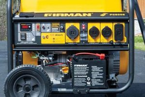
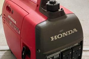
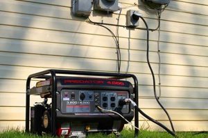
A schematic representation illustrates the electrical connections and pathways within a compact, transportable power source. This visual guide typically details the flow of electricity from the generator’s engine to its various outlets and control components, including circuit breakers, voltage regulators, and grounding systems. An example would depict the wiring for a common household generator, showing how the alternator connects to the control panel and subsequently to the receptacles providing power.
Understanding the electrical layout of such power sources is paramount for safe operation and effective troubleshooting. Properly interpreting these schematics ensures correct connections, preventing damage to the equipment and minimizing the risk of electrical hazards. Historically, access to these visual guides was primarily limited to trained technicians. However, with increasing accessibility of information, users now have more resources to comprehend the inner workings of their equipment, facilitating better maintenance and informed decision-making during operation.
This understanding forms the foundation for topics such as generator maintenance, troubleshooting common electrical issues, and safe operating procedures. Further exploration of these areas will equip users with the knowledge to effectively and safely utilize their independent power supply.
Tips for Working with Generator Wiring Diagrams
Careful consideration of wiring diagrams is essential for safe and effective generator operation. These tips provide guidance for interpreting and utilizing these crucial schematics.
Tip 1: Locate the Correct Diagram: Generator models vary. Ensure the diagram precisely matches the specific make and model of the generator in use. Using an incorrect diagram can lead to faulty connections and potential hazards.
Tip 2: Understand Standard Symbols: Familiarize oneself with common electrical symbols representing components like switches, fuses, and ground connections. Misinterpreting symbols can result in incorrect wiring.
Tip 3: Trace the Circuit Path: Follow the lines on the diagram to understand the flow of electricity from the power source to the output receptacles. This helps in troubleshooting and identifying potential issues.
Tip 4: Pay Attention to Wire Colors and Gauges: Diagrams often indicate wire colors corresponding to specific functions (e.g., hot, neutral, ground). Wire gauge relates to current-carrying capacity. Using incorrect wiring can lead to overheating and potential fire hazards.
Tip 5: Consult Qualified Professionals When Necessary: Complex wiring modifications or repairs should be undertaken by qualified electricians. Attempting intricate work without proper training can create safety risks and damage the generator.
Tip 6: Keep the Diagram Accessible: Store the wiring diagram in a safe, easily accessible location near the generator. This allows for quick reference during maintenance or troubleshooting.
Tip 7: Double-Check Connections: Before energizing the generator, meticulously verify all connections against the diagram. A simple oversight can lead to malfunction or create hazardous conditions.
Adhering to these guidelines ensures safe and proper generator operation, maximizing its lifespan and minimizing potential risks. Careful attention to wiring details contributes significantly to reliable power generation.
By understanding and applying these tips, individuals can confidently approach generator maintenance and troubleshooting, ensuring a safe and reliable power supply.
1. Safety
Safe operation of portable generators is paramount, requiring a thorough understanding of their electrical systems. A wiring diagram provides a crucial visual representation of these systems, directly impacting safe practices and hazard prevention. Ignoring or misinterpreting the diagram can lead to serious consequences, including electrical shock, fire, and equipment damage.
- Grounding
Proper grounding, as depicted in the wiring diagram, is essential to prevent electrical shock. The diagram illustrates the grounding path, ensuring correct connection to a grounding rod or designated grounding point. A faulty ground connection, often revealed through careful diagram analysis, can create a dangerous potential for electrical shock. For example, a missing ground wire connection, easily identified on the diagram, could energize the generator’s frame, posing a severe hazard to anyone touching it.
- Overload Protection
Wiring diagrams illustrate the location and function of circuit breakers and fuses, critical components for overload protection. Exceeding the generator’s rated wattage, a scenario clarified by the diagram’s wattage specifications, can lead to overheating and potential fire. The diagram aids in understanding the current flow and capacity limitations of various circuits. For instance, connecting too many appliances to a single circuit, easily visualized on the diagram, can trip a breaker, preventing a potential overload situation.
- Connection Integrity
Secure and correct wiring connections, as specified in the diagram, prevent shorts and open circuits. Loose or incorrectly wired connections, easily misidentified without referencing the diagram, can lead to sparks, overheating, and potential fires. For example, connecting a wire to the wrong terminal, clearly indicated on the diagram, can create a short circuit, causing damage to the generator and potentially igniting flammable materials.
- Environmental Hazards
The wiring diagram indirectly contributes to environmental safety. Understanding the generators electrical system allows for proper operation, minimizing the risk of fuel spills and carbon monoxide poisoning. For example, correct wiring, guided by the diagram, ensures efficient generator function, reducing the chances of fuel leakage from a malfunctioning unit. This, in turn, minimizes environmental contamination and fire hazards.
Careful adherence to the information presented in a portable generator wiring diagram is fundamental to safe operation. Understanding its components, connections, and protective measures mitigates risks, ensuring the well-being of users and preventing potential hazards. Neglecting this crucial resource can lead to serious consequences, underscoring the importance of consulting and understanding the diagram before operating any portable generator.
2. Troubleshooting
Effective troubleshooting of portable generators relies heavily on a comprehensive understanding of the corresponding wiring diagram. The diagram serves as a roadmap of the electrical system, enabling systematic diagnosis of malfunctions. Cause-and-effect relationships within the generator’s circuitry are clearly illustrated, allowing one to trace the flow of electricity and pinpoint the source of issues. For example, a generator failing to produce power might be traced back to a faulty connection between the alternator and the main output breaker, a detail readily apparent on the wiring diagram. Without the diagram, troubleshooting becomes a process of guesswork, potentially leading to incorrect repairs or further damage.
The wiring diagram’s role in troubleshooting extends beyond simple component failures. It facilitates understanding of the generator’s protective mechanisms, such as circuit breakers and fuses. For instance, a tripped breaker, indicated on the diagram, points towards an overloaded circuit, guiding the user to reduce the connected load rather than simply resetting the breaker and potentially causing further damage. Moreover, the diagram assists in identifying more complex issues, such as voltage fluctuations or erratic operation, by enabling systematic checks of voltage regulator connections and other control circuitry. This systematic approach, facilitated by the diagram, saves time and reduces the risk of misdiagnosis.
In conclusion, the wiring diagram stands as an indispensable tool for troubleshooting portable generators. Its detailed illustration of the electrical system empowers users to methodically identify and resolve malfunctions, minimizing downtime and preventing further damage. Proficiency in interpreting these diagrams translates directly to effective maintenance and repair, ensuring reliable generator operation. Ignoring or misinterpreting the diagram, conversely, can lead to inefficient troubleshooting, potentially exacerbating problems and increasing repair costs. Therefore, understanding the wiring diagram represents a crucial competency for anyone operating or maintaining a portable generator.
3. Maintenance
Effective maintenance of a portable generator hinges on a thorough understanding of its wiring diagram. This schematic serves as a crucial reference point for various maintenance procedures, guiding technicians and users alike through the intricacies of the electrical system. Without a firm grasp of the wiring diagram, maintenance tasks become significantly more challenging, increasing the risk of errors and potentially compromising the generator’s performance and safety.
- Visual Inspection
Wiring diagrams facilitate visual inspections by providing a clear layout of the electrical components and their connections. This allows for easy identification of loose wires, damaged insulation, or signs of overheating. For example, a frayed wire near the alternator, readily identifiable on the diagram, can be addressed before it causes a major malfunction. Without the diagram, such issues might go unnoticed, potentially leading to costly repairs or safety hazards.
- Component Replacement
When components require replacement, the wiring diagram becomes an indispensable guide. It precisely identifies the location and wiring configuration of each part, ensuring correct installation of the new component. For instance, replacing a faulty voltage regulator requires careful attention to its wiring connections, clearly depicted in the diagram. Incorrect wiring, due to a lack of diagram consultation, could damage the new regulator or other parts of the generator’s electrical system.
- Cleaning and Lubrication
While not directly related to wiring, the diagram provides context for cleaning and lubrication procedures. By understanding the layout of components and their interconnections, one can avoid inadvertently damaging sensitive electrical parts during these maintenance tasks. For instance, knowing the location of electrical connectors, as shown on the diagram, allows for careful cleaning around those areas, preventing the introduction of moisture or debris.
- Preventative Maintenance
The wiring diagram aids in preventative maintenance by enabling a proactive approach to identifying potential issues. Regular review of the diagram can familiarize users with the electrical system, allowing for early detection of wear and tear or potential problem areas. For example, understanding the current path through various circuits, as illustrated in the diagram, helps anticipate potential overload points, prompting preventative measures like load balancing or circuit upgrades.
In summary, the wiring diagram plays a vital role in all aspects of portable generator maintenance. From visual inspections and component replacement to preventative measures, understanding the electrical schematic contributes significantly to the longevity and reliable performance of the generator. Neglecting the wiring diagram during maintenance increases the likelihood of errors, potentially leading to costly repairs, safety hazards, and reduced generator lifespan. Therefore, consistent reference to the wiring diagram should be an integral part of any portable generator maintenance routine.
4. Component Identification
Accurate component identification is essential for effective maintenance, troubleshooting, and repair of portable generators. The wiring diagram serves as the primary resource for this identification, providing a detailed visual representation of each component’s location, function, and interconnection within the system. Without a thorough understanding of the diagram and the symbols it employs, misidentification of components is likely, potentially leading to incorrect repairs, further damage, and safety hazards.
- Alternator
The alternator, often represented by a circular symbol with internal windings, is the heart of the generator, responsible for producing electrical power. The wiring diagram illustrates its connection to the engine and the subsequent flow of electricity to the output terminals. Correctly identifying the alternator and its associated wiring is crucial for diagnosing charging system issues or replacing the unit itself. For example, a faulty connection between the alternator and the voltage regulator, readily identifiable on the diagram, could explain low output voltage.
- Voltage Regulator
The voltage regulator, typically depicted as a rectangular box with connection points, maintains stable output voltage. The diagram reveals its connection to the alternator and control circuitry. Understanding its location and wiring is vital for troubleshooting voltage fluctuations. For instance, a burnt connection on the voltage regulator, identifiable through the diagram, could be the root cause of unstable power delivery.
- Circuit Breakers and Fuses
Circuit breakers and fuses, often symbolized by switches or segmented lines, protect the generator from overloads. The diagram pinpoints their positions within the circuitry and the specific circuits they protect. Correct identification is crucial for safely resetting tripped breakers or replacing blown fuses. Attempting to bypass these safety devices, easily misinterpreted without consulting the diagram, can create significant fire hazards.
- Output Receptacles
Output receptacles, represented by standardized symbols, provide the connection points for powering external devices. The wiring diagram illustrates their connection to the generator’s internal circuitry, including the associated wiring gauge and circuit protection. Accurate identification ensures correct usage and prevents overloading individual circuits. For instance, connecting a high-power appliance to a receptacle intended for lower wattage, easily misjudged without referencing the diagram, could overload the circuit and trip a breaker.
In conclusion, the wiring diagram acts as a crucial key for accurate component identification within a portable generator. This precise identification is fundamental for effective troubleshooting, maintenance, and repair. By utilizing the diagram to locate and understand the function of each component, users can confidently address issues and ensure the safe and reliable operation of their generator. Failure to consult the diagram risks misidentification, potentially leading to incorrect repairs and further complications.
5. Connection Integrity
Connection integrity is paramount for the safe and reliable operation of a portable generator. The wiring diagram serves as the blueprint for ensuring this integrity, providing a detailed visual representation of every connection within the electrical system. Compromised connection integrity, often stemming from deviations from the prescribed wiring diagram, can lead to a cascade of issues, ranging from inefficient operation to severe safety hazards.
- Wire Termination
Proper wire termination, as depicted in the wiring diagram, is crucial for secure and reliable electrical connections. This includes using the correct crimping tools, connectors, and techniques to ensure a tight and lasting bond. A poorly terminated wire, easily overlooked without referencing the diagram’s specifications, can lead to increased resistance, overheating, and potential fire hazards. For instance, a loose connection at the alternator’s output terminal, clearly illustrated in the diagram, could cause significant power loss and potential damage to the generator.
- Connector Selection
Choosing the correct connectors, as specified in the wiring diagram, is essential for maintaining connection integrity. Different connectors are designed for specific wire gauges and environmental conditions. Using an incompatible connector, a mistake easily made without careful diagram consultation, can result in loose connections, corrosion, and eventual failure. For example, using a connector not rated for outdoor use, a detail often specified in the diagram, can lead to rapid deterioration in damp environments, compromising the connection and potentially creating a shock hazard.
- Insulation Quality
Maintaining the integrity of wire insulation, as emphasized in the wiring diagram, prevents short circuits and ensures safe operation. Damaged or deteriorated insulation, often difficult to detect without a thorough visual inspection guided by the diagram, can expose live wires, creating a risk of electrical shock or fire. A chafed wire near a metal frame component, easily missed without referencing the diagram’s layout, can create a direct short, potentially damaging the generator and posing a significant safety risk.
- Environmental Protection
Protecting connections from environmental factors, as indicated by the wiring diagram, is crucial for long-term reliability. This might involve using weatherproof enclosures, sealant, or specialized connectors. Neglecting these protective measures, often detailed within the diagram or accompanying documentation, can lead to corrosion, shorts, and eventual failure. For instance, failing to seal connections exposed to the elements, a precaution often highlighted in the diagram, can result in rapid deterioration and malfunction, especially in harsh environments.
In conclusion, connection integrity, as meticulously detailed in the portable generator wiring diagram, is fundamental for safe and reliable operation. Each connection, from the smallest wire termination to the largest power cable, plays a critical role in the overall performance and safety of the generator. Ignoring or deviating from the wiring diagram compromises this integrity, increasing the risk of malfunctions, safety hazards, and costly repairs. Therefore, adhering to the wiring diagram’s specifications is not merely a recommendation but a critical requirement for responsible generator ownership and operation.
Frequently Asked Questions
This section addresses common inquiries regarding portable generator wiring diagrams, providing clear and concise answers to facilitate understanding and safe operation.
Question 1: Where can one locate the correct wiring diagram for a specific portable generator model?
The correct wiring diagram is typically found in the owner’s manual provided with the generator. Manufacturers’ websites often offer digital versions of these manuals for download. Contacting the manufacturer directly is another viable option for obtaining the necessary diagram.
Question 2: What are the standard symbols used in portable generator wiring diagrams, and where can one find explanations for these symbols?
Standard electrical symbols represent components like switches, fuses, resistors, and ground connections. Most owner’s manuals include a legend explaining these symbols. Numerous online resources and electrical textbooks also offer comprehensive guides to standard electrical symbology.
Question 3: How does one interpret the wiring diagram to understand the generator’s electrical system and its various components?
Interpreting a wiring diagram involves tracing the lines representing wires to understand the flow of electricity between components. The diagram indicates the connections between the engine, alternator, control panel, and output receptacles, allowing for a comprehensive understanding of the electrical pathways.
Question 4: What are the potential risks associated with misinterpreting or ignoring the wiring diagram during maintenance or repairs?
Misinterpreting or ignoring the wiring diagram can lead to incorrect connections, potentially causing damage to the generator, creating safety hazards such as electrical shock or fire, and voiding warranties. Serious injury or property damage could result from improper handling of electrical components.
Question 5: When should a qualified electrician be consulted for assistance with generator wiring?
Complex wiring modifications, repairs involving the generator’s internal circuitry, or any situation involving uncertainty regarding the wiring diagram necessitates consultation with a qualified electrician. Attempting complex electrical work without proper training and experience can be dangerous and lead to further damage.
Question 6: How can one ensure the long-term integrity of wiring connections within a portable generator?
Ensuring long-term connection integrity requires using appropriate connectors, proper crimping techniques, maintaining insulation quality, and protecting connections from environmental factors such as moisture and corrosion. Regular inspection and maintenance, guided by the wiring diagram, contribute significantly to the longevity and reliability of electrical connections.
Understanding and correctly interpreting the wiring diagram is essential for the safe and effective use of a portable generator. These FAQs offer guidance on common concerns. However, they do not substitute for professional advice. Consulting a qualified electrician is always recommended for complex issues or when in doubt.
This concludes the frequently asked questions section. The next section will cover practical applications of understanding portable generator wiring diagrams.
Conclusion
Careful examination of portable generator wiring diagrams reveals their crucial role in safe operation, effective troubleshooting, and proper maintenance. These schematics provide a detailed visual representation of the generator’s electrical system, empowering users to understand the flow of electricity, identify components, and ensure proper connections. From the alternator to the output receptacles, every wire and connection plays a vital role in the generator’s performance and safety. Understanding these intricacies, as depicted in the wiring diagram, enables informed decision-making during operation and maintenance, preventing potential hazards and ensuring reliable power generation.
The significance of consulting and comprehending these diagrams cannot be overstated. Neglecting this crucial resource risks misdiagnosis, improper repairs, and potential safety hazards. Competency in interpreting wiring diagrams translates directly to responsible generator ownership, promoting safe practices and maximizing the generator’s lifespan. Continued emphasis on understanding these schematics will undoubtedly contribute to enhanced safety and reliability within the portable generator landscape.

