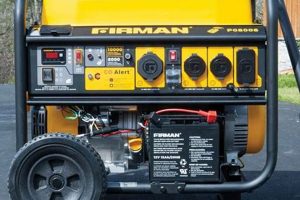
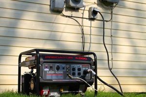
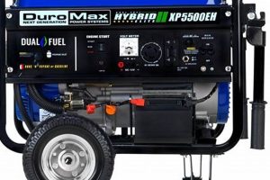
A diagram illustrating the electrical connections and components within a compact, transportable power source provides a visual representation of the unit’s internal workings. This visual guide typically details the pathways of electrical current, the arrangement of components like the engine, alternator, fuel system, and control panel, and the connections between them. For instance, it might illustrate how the engine’s rotational energy is converted into electricity by the alternator, and how that electricity is then regulated and distributed to the output receptacles.
Such diagrams are essential for troubleshooting, repair, and maintenance of these power sources. Understanding the interplay of components allows for efficient diagnosis of faults, enabling targeted repairs and minimizing downtime. Historically, these diagrams were primarily used by technicians and engineers. However, with the increasing prevalence of these units, access to and understanding of such representations has become more widespread among users who perform their own maintenance or require a deeper understanding of their equipment’s operation.
This understanding is crucial for safe and effective operation. The following sections delve into specific aspects of these compact power generation systems, covering topics such as safety precautions, proper maintenance procedures, and common troubleshooting techniques. Further exploration will also address the selection and sizing of these units for various applications.
Tips for Utilizing Diagrams of Portable Power Sources
Effective use of electrical diagrams for compact, transportable generators requires careful attention to detail and a systematic approach. The following tips provide guidance for interpreting and applying these valuable resources.
Tip 1: Safety First: Always disconnect the power source from any fuel and electrical loads before consulting or working with its internal wiring diagram. This mitigates the risk of electrical shock or unintended operation.
Tip 2: Identify the Specific Model: Diagrams are model-specific. Ensure the diagram matches the exact make and model of the generator to avoid inaccuracies and potential misdiagnosis.
Tip 3: Understand Symbolism: Familiarize oneself with standard electrical symbols used in these diagrams. A legend often accompanies the diagram explaining the meaning of each symbol.
Tip 4: Trace the Circuitry: Follow the flow of current as depicted in the diagram to understand the interconnectedness of components. This aids in troubleshooting and isolating faulty parts.
Tip 5: Cross-Reference with the Manual: Use the diagram in conjunction with the owner’s manual for comprehensive guidance on maintenance, troubleshooting, and repair procedures.
Tip 6: Consult Qualified Professionals: For complex issues or if uncertainty arises, seek assistance from qualified technicians. Attempting repairs beyond one’s expertise can lead to further damage or safety hazards.
Tip 7: Keep Diagrams Accessible: Store the diagram and owner’s manual in a readily accessible location for quick reference when needed.
Adhering to these guidelines ensures the safe and effective application of diagrammatic representations for maintaining and troubleshooting portable power generation equipment. Proper interpretation of these diagrams empowers users with the knowledge necessary to keep their equipment running smoothly and safely.
By understanding and applying these principles, users can maximize the lifespan and reliability of their portable power sources. The subsequent conclusion will reiterate the importance of proper maintenance and safe operating practices.
1. Visual Representation
Visual representation forms the core of a portable generator schematic, transforming abstract electrical concepts into a concrete, understandable format. This graphical depiction translates the complex interplay of components and circuits into a readily interpretable form. The schematic’s efficacy hinges on its ability to clearly illustrate the generator’s internal organization, facilitating comprehension of its functionality. For instance, the depiction of the alternator’s connection to the voltage regulator visually clarifies how output voltage is stabilized, a relationship difficult to grasp from textual descriptions alone. This visual clarity empowers users to diagnose issues effectively, trace electrical pathways, and understand the system’s overall operation.
The schematic’s value extends beyond basic comprehension. It serves as a crucial tool for troubleshooting. Consider a scenario where a generator fails to produce power. By tracing the circuit pathways depicted in the schematic, one can pinpoint potential breaks or faulty connections, leading to a targeted repair. This visual guide significantly reduces diagnostic time and enhances repair efficiency. Furthermore, a clear visual representation contributes to preventative maintenance. Understanding the layout of components facilitates inspection and cleaning, contributing to the generator’s longevity and reliable operation. For example, the schematic can highlight the location of brushes within the alternator, prompting regular checks for wear and tear.
In conclusion, the effectiveness of a portable generator schematic rests upon its clarity of visual representation. This visual language translates complex electrical principles into an accessible format, enabling users to understand, diagnose, and maintain their equipment effectively. Challenges in interpreting schematics can arise from variations in symbology or complexity of the depicted system. However, overcoming these challenges through careful study and consultation of accompanying documentation significantly enhances one’s ability to leverage the schematic’s full potential, ensuring the safe and efficient operation of the generator.
2. Component Identification
Component identification is inextricably linked to the effective utilization of a portable generator schematic. The schematic serves as a roadmap, visually representing the generator’s internal components and their interconnections. Accurate component identification is essential for several reasons: troubleshooting, maintenance, and safe operation. Without the ability to identify components based on their schematic representation, diagnosing faults becomes a guessing game, potentially leading to incorrect repairs or further damage. For instance, misidentifying the voltage regulator as a capacitor could lead to improper testing and replacement, exacerbating the original problem. Understanding the location and function of each component, as depicted in the schematic, is the foundation upon which effective troubleshooting and maintenance are built.
Consider a scenario involving a malfunctioning fuel system. The schematic provides a visual representation of the fuel tank, fuel lines, fuel pump, and carburetor. Correctly identifying these components allows for a systematic check for leaks, blockages, or malfunctions. This targeted approach, guided by the schematic and accurate component identification, saves valuable time and resources compared to a haphazard inspection. Similarly, during routine maintenance, proper component identification ensures that the correct procedures are applied to each part. Lubricating the wrong component or using incorrect cleaning agents can lead to premature wear and tear, reducing the generator’s lifespan.
In summary, the relationship between component identification and the portable generator schematic is symbiotic. The schematic provides the visual guide, while accurate component identification unlocks the schematic’s potential for effective troubleshooting, maintenance, and safe operation. Challenges in component identification can arise from variations in schematic symbology or complex component layouts. Overcoming these challenges requires careful study of the schematic, cross-referencing with the generator’s user manual, and potentially consulting expert resources. Mastering component identification empowers users to confidently address maintenance needs and diagnose faults, ultimately contributing to the safe and reliable operation of the portable generator.
3. Wiring Pathways
Wiring pathways within a portable generator schematic constitute the circulatory system of the unit, depicting the flow of electrical current throughout its components. Understanding these pathways is paramount for effective troubleshooting, maintenance, and safe operation. The schematic acts as a guide, illustrating the intricate network of wires and connections that facilitate power generation and distribution.
- Current Flow Visualization:
Wiring pathways within the schematic illustrate the direction and distribution of electrical current from the generator’s core components, such as the alternator and voltage regulator, to the output receptacles. This visual representation allows for a clear understanding of how power is generated, regulated, and delivered. For example, tracing the pathway from the alternator windings through the rectifier and voltage regulator reveals the stages of power transformation and stabilization. This understanding is fundamental for diagnosing output voltage issues or power fluctuations.
- Component Interconnection:
The schematic’s depiction of wiring pathways reveals the interconnectivity of various components within the generator. This interconnectedness is critical for understanding how different parts of the system influence each other. For example, the connection between the engine’s ignition system and the alternator’s field windings demonstrates the dependency of electrical generation on the engine’s operation. Recognizing these connections allows for a holistic approach to troubleshooting, enabling technicians to identify the root cause of malfunctions more effectively.
- Safety Interlocks and Protection:
Wiring pathways also illustrate the integration of safety features like circuit breakers, fuses, and grounding systems. These safety mechanisms protect the generator and the user from overloads, short circuits, and electrical shocks. The schematic clarifies the role of each safety component within the overall circuit. For instance, tracing the grounding pathway highlights its role in diverting fault currents away from the user and preventing electrical hazards. Understanding these pathways reinforces the importance of maintaining the integrity of these safety features.
- Troubleshooting and Repair Guidance:
A clear understanding of wiring pathways, as depicted in the schematic, is indispensable for effective troubleshooting and repair. When a fault occurs, the schematic provides a roadmap for tracing the affected circuit and isolating the problem. For example, if an output receptacle fails to deliver power, the schematic allows one to systematically check the wiring pathway from the receptacle back to the power source, identifying any breaks or loose connections along the way. This targeted approach minimizes downtime and ensures accurate repairs.
In essence, wiring pathways within a portable generator schematic provide a crucial visual representation of the electrical system’s architecture. This understanding is foundational for effective maintenance, troubleshooting, and ensuring safe operation. By accurately interpreting the depicted pathways, users can diagnose faults, implement preventative maintenance measures, and operate the generator with confidence, maximizing its lifespan and reliability.
4. Troubleshooting Guide
A troubleshooting guide relies heavily on the portable generator schematic for effective diagnosis and repair of operational issues. The schematic provides the foundational visual representation of the generator’s internal systems, enabling the guide to direct users through a logical, step-by-step process of fault isolation. Cause and effect relationships between symptoms and underlying problems become clear through the schematic’s depiction of component interconnections and wiring pathways. For example, a troubleshooting guide might reference the schematic to explain how a faulty voltage regulator can cause fluctuating output voltage. Without the schematic, the guide would lack the visual context necessary to pinpoint the source of such an issue.
The importance of the schematic as a component of a troubleshooting guide is further exemplified in situations involving complex electrical faults. Consider a scenario where a generator experiences intermittent power loss. The troubleshooting guide, referencing the schematic, might direct the user to inspect specific wiring connections, test the output of the alternator, or examine the fuel system components. Each step relies on the schematic’s visual representation to guide the user to the relevant area within the generator. The schematic transforms abstract troubleshooting steps into concrete actions, localized within the physical machine. Practical application of this understanding empowers users to diagnose and resolve issues effectively, minimizing downtime and maximizing the generator’s operational lifespan. A well-illustrated guide, paired with a detailed schematic, can significantly reduce repair costs by empowering users to perform basic maintenance and troubleshooting themselves.
In summary, the troubleshooting guide and portable generator schematic form a synergistic partnership. The schematic provides the visual framework, while the guide utilizes this framework to direct users through a logical diagnostic process. This relationship is fundamental for effective troubleshooting and repair. Challenges may arise when schematics are overly complex or poorly documented. However, a well-designed troubleshooting guide, coupled with a clear and accurate schematic, equips users with the knowledge and confidence necessary to address a wide range of operational issues, ensuring the reliable and sustained performance of the portable generator. This understanding ultimately contributes to user safety by guiding correct diagnostic and repair procedures, reducing the risk of accidental damage or injury.
5. Maintenance Aid
Preventative maintenance ensures the longevity and reliability of portable generators. A comprehensive understanding of the unit’s internal workings, facilitated by a detailed schematic, is essential for effective maintenance. The schematic acts as a roadmap, guiding users through the intricacies of the generator’s systems and enabling targeted maintenance procedures. This understanding translates directly into improved performance, reduced downtime, and enhanced safety.
- Component Inspection and Lubrication:
Schematics provide precise locations and configurations of components requiring regular inspection and lubrication. For example, the schematic highlights the location of bearings within the alternator, enabling targeted lubrication and preventing premature wear. This targeted approach, guided by the schematic, ensures that critical components receive the necessary attention, maximizing their operational lifespan.
- Fuel System Maintenance:
Fuel system components, including the fuel tank, fuel lines, fuel filter, and carburetor, are clearly depicted in the schematic. This visual representation guides users through fuel system maintenance procedures, such as fuel filter replacement or carburetor cleaning. Understanding the fuel system layout, as depicted in the schematic, facilitates safe and effective maintenance practices, preventing fuel leaks and ensuring optimal engine performance.
- Electrical System Checks:
The schematic illustrates the wiring pathways and connections within the electrical system. This visual representation facilitates checks for loose connections, corroded terminals, and damaged wiring. Regular inspection of these elements, guided by the schematic, prevents electrical faults, ensuring safe and reliable power delivery.
- Cooling System Maintenance:
The schematic details the components of the cooling system, such as the cooling fins, fan, and airflow pathways. This visual guide facilitates proper cleaning and inspection of these components, ensuring efficient heat dissipation and preventing overheating. Regular maintenance of the cooling system, guided by the schematic, contributes to the generator’s longevity and prevents performance degradation due to excessive heat.
In conclusion, the portable generator schematic serves as an indispensable maintenance aid, guiding users through the complexities of the machine’s internal systems. This detailed visual representation empowers users to perform targeted maintenance procedures, ensuring optimal performance, extending the generator’s lifespan, and promoting safe operation. The schematic bridges the gap between abstract maintenance concepts and practical application, transforming users into informed maintainers capable of preserving the integrity and functionality of their portable power generation equipment.
6. Safety Reference
A portable generator schematic functions as a critical safety reference, providing crucial information for safe operation and maintenance. The schematic visually represents the generator’s internal components, wiring, and safety features, enabling users to understand potential hazards and mitigate risks. This visual guide is essential for preventing accidents and ensuring proper handling of the equipment. Cause and effect relationships between specific actions and potential safety consequences are often illustrated within the schematic or accompanying documentation. For instance, the schematic may highlight the grounding system, emphasizing its role in preventing electrical shocks. Ignoring this highlighted safety feature could lead to severe injury. The schematic’s role as a safety reference becomes particularly crucial during maintenance procedures. Disconnecting the spark plug wire, as indicated in the schematic, before servicing the engine prevents accidental starting and potential injury. Real-life examples abound where neglecting schematic-guided safety precautions have resulted in accidents, underscoring the importance of consulting the schematic as a primary safety reference. One example involves improper fuel handling, leading to fires or explosions. The schematic often details safe fuel storage and handling procedures, mitigating such risks.
Further analysis reveals the schematic’s contribution to safe troubleshooting practices. By visually representing the electrical system, the schematic guides users to safely test circuits and isolate faults, reducing the risk of electrical shock. For instance, the schematic might indicate safe test points within the circuit, preventing accidental contact with live wires. The practical significance of this understanding is readily apparent. Properly grounding the generator, as depicted in the schematic, protects users from electrical hazards during operation. Similarly, understanding the fuel system layout from the schematic aids in safe refueling procedures, minimizing the risk of spills and fires. Practical applications extend to maintenance tasks such as oil changes or air filter replacements. The schematic guides users to safely access and service these components, reducing the risk of burns or other injuries.
In conclusion, the portable generator schematic serves as an indispensable safety reference, providing critical information for safe operation, maintenance, and troubleshooting. Its visual representation of internal components, wiring, and safety features empowers users to identify and mitigate potential hazards. Challenges in interpreting schematics can arise due to variations in symbology or complexity of the depicted system. However, overcoming these challenges through careful study and consultation of accompanying documentation significantly enhances one’s ability to leverage the schematic for safe and effective generator operation. This proactive approach to safety, guided by the schematic, minimizes risks and promotes a secure operating environment.
Frequently Asked Questions
The following addresses common inquiries regarding diagrams for portable generators.
Question 1: Where can one locate a diagram specific to a particular generator model?
Manufacturer websites often provide access to manuals and diagrams. Alternatively, contacting the manufacturer directly or consulting authorized service centers can yield the required documentation.
Question 2: What are the key components typically depicted in these diagrams?
Essential components include the engine, alternator, fuel system (tank, lines, carburetor), control panel, voltage regulator, and various safety features like circuit breakers and grounding systems. Wiring pathways and connections between these components are also typically illustrated.
Question 3: How can one interpret the symbols and abbreviations used in these diagrams?
A legend accompanying the diagram typically explains the meaning of various symbols and abbreviations. Standard electrical symbols are often used, which can also be found in electrical engineering textbooks or online resources.
Question 4: How does a diagram assist in troubleshooting common generator issues?
By visually tracing the circuitry and connections, one can identify potential points of failure. For example, a lack of output voltage might be traced back to a faulty connection, a malfunctioning voltage regulator, or issues within the alternator itself.
Question 5: Can these diagrams aid in performing routine maintenance?
Diagrams assist in locating components requiring regular maintenance, such as lubrication points, air filters, and spark plugs. Understanding the layout of the fuel system also facilitates safe and effective fuel filter replacements or carburetor cleaning.
Question 6: How do these diagrams contribute to safe generator operation?
Diagrams illustrate the location and function of safety features, such as grounding points and circuit breakers. Understanding these features is crucial for preventing electrical shocks and protecting the equipment from damage. Additionally, diagrams often depict safe handling procedures for fuel and other potentially hazardous materials.
Understanding these key aspects of portable generator diagrams facilitates effective troubleshooting, maintenance, and safe operation. This knowledge contributes to the longevity and reliability of the equipment.
The following section provides a practical guide to using these diagrams for various applications.
Conclusion
Portable generator schematics provide invaluable insight into the intricate workings of these power sources. Exploration of component identification, wiring pathways, troubleshooting procedures, maintenance guidelines, and safety considerations underscores the significance of these diagrams. Understanding these visual representations empowers users with the knowledge necessary for effective operation, maintenance, and repair, ultimately contributing to the longevity and reliability of the equipment.
Emphasis on proper utilization of portable generator schematics remains paramount for safe and efficient power generation. Continued study and application of these principles will ensure reliable performance and mitigate potential hazards associated with improper handling or maintenance. The schematic serves as a critical resource, enabling informed decision-making and promoting responsible equipment ownership.


