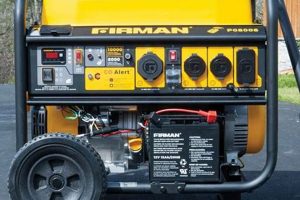
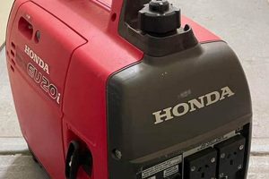
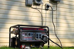
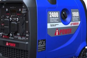
A visual representation of a compact, mobile power source’s components, typically illustrating their arrangement and interconnection, serves as a crucial tool for understanding, maintaining, and repairing the equipment. Such a representation often utilizes labels and symbols to identify individual parts like the engine, alternator, fuel tank, and control panel, clarifying their relationships within the overall system. An example would be a schematic showing the fuel lines connecting the tank to the carburetor and the wiring harness connecting the alternator to the control panel.
Access to a clear illustration of a compact power source’s internal structure is essential for effective troubleshooting, repair, and maintenance. It allows users to quickly locate components, understand their function within the system, and diagnose potential issues. This visual aid is invaluable for both professionals servicing the equipment and individuals undertaking DIY repairs. Historically, these representations were primarily found in service manuals; however, the internet has significantly broadened their availability, simplifying the maintenance process for a wider audience. This accessibility empowers users to take ownership of their equipment’s upkeep and potentially reduce repair costs.
Understanding the internal workings of these power sources is paramount for safe and efficient operation. The subsequent sections will delve into specific components, common maintenance procedures, and troubleshooting techniques, providing a comprehensive guide to maintaining and repairing these valuable devices.
Tips for Utilizing Compact Power Source Component Illustrations
Effective use of visual representations of compact power source components is crucial for successful maintenance and repair. The following tips provide guidance on maximizing the benefits of these diagrams.
Tip 1: Obtain the Correct Diagram. Ensure the illustration corresponds precisely to the specific make and model of the equipment. Variations exist even within the same brand, and using an incorrect diagram can lead to misidentification of components.
Tip 2: Familiarize with the Legend. Diagrams often employ symbols and abbreviations. Understanding the legend is essential for accurate interpretation of the illustration.
Tip 3: Use the Diagram Systematically. When troubleshooting, trace the flow of energy or fuel through the system on the diagram to isolate the potential problem area.
Tip 4: Keep the Diagram Clean and Accessible. Store a printed copy in a protective sleeve near the equipment or bookmark the digital version for easy reference.
Tip 5: Refer to the Diagram During Disassembly and Reassembly. This practice helps prevent errors and ensures all components are correctly reinstalled.
Tip 6: Supplement the Diagram with the Owner’s Manual. The owner’s manual often contains additional information regarding specific component locations and maintenance procedures.
Tip 7: Utilize Online Resources. Many manufacturers and online communities offer interactive diagrams and troubleshooting guides that can complement the basic diagram.
Proper utilization of these visual aids ensures accurate diagnoses, efficient repairs, and prolonged equipment lifespan. These practices promote safe and effective maintenance, reducing the risk of damage and optimizing performance.
By understanding and applying these tips, individuals can confidently maintain their equipment, minimizing downtime and maximizing its utility. The following section will provide concluding remarks and further resources for continued learning.
1. Identification
Accurate component identification is fundamental to effective use of a portable generator parts diagram. A diagram serves as a roadmap, but its utility depends on precisely identifying individual components. This process forms the basis for all subsequent diagnostic and maintenance procedures.
- Visual Recognition:
Diagrams often depict components realistically or schematically. Visual recognition involves matching the representation on the diagram to the physical component on the generator. For example, the alternator, often cylindrical with distinct wiring connections, can be located by comparing its visual characteristics to the diagram representation. Correct visual identification prevents misdiagnosis and incorrect part replacement.
- Part Number Verification:
Many diagrams incorporate part numbers. These alphanumeric codes provide definitive identification, eliminating ambiguity arising from similar-looking components. Cross-referencing the part number on the diagram with the number on the physical component confirms accurate identification. This is critical when ordering replacement parts, ensuring the correct part is obtained.
- Nomenclature and Terminology:
Understanding the specific terminology used in the diagram is crucial. Terms like “stator,” “rotor,” or “carburetor” must be accurately understood to locate and identify corresponding parts. Consulting a glossary or the generator’s manual can clarify unfamiliar terms, further enhancing identification accuracy.
- Location and Orientation:
Diagrams illustrate the location and orientation of components within the generator. Understanding these spatial relationships assists in physically locating components. For instance, knowing the fuel pump is situated adjacent to the fuel tank narrows the search area. Accurate location and orientation understanding are vital for efficient maintenance and repair.
These facets of identification collectively empower effective utilization of a portable generator parts diagram. Precise component identification is the foundation for accurate troubleshooting, effective repairs, and overall successful generator maintenance. Without accurate identification, the diagram’s utility is significantly diminished, increasing the risk of incorrect diagnoses and ineffective repairs.
2. Location
Understanding the spatial arrangement of components within a portable generator is critical for effective maintenance and repair. A parts diagram provides this crucial spatial context, linking individual components to their physical locations within the unit. This understanding facilitates efficient troubleshooting, part replacement, and overall system comprehension.
- Component Placement:
Diagrams illustrate the precise placement of each component within the generator’s structure. This information is essential for locating specific parts during maintenance or repair. For example, knowing the oil dipstick is located near the engine’s crankcase simplifies the oil level check. Without this spatial awareness, locating components can become a time-consuming and potentially frustrating process.
- Accessibility and Disassembly:
The diagram informs access procedures for specific components. Understanding the location of access panels, fasteners, and surrounding components streamlines disassembly and reassembly. For instance, knowing the air filter is accessed through a specific panel on the generator’s housing reduces unnecessary disassembly. This knowledge saves time and minimizes the risk of damaging other components during maintenance.
- Interconnections and Wiring:
Diagrams often illustrate the routing of wiring harnesses, fuel lines, and other connections between components. Understanding these pathways is essential for tracing faults, replacing damaged lines, or understanding the system’s overall functionality. For example, tracing the spark plug wire from the coil to the spark plug on the diagram aids in diagnosing ignition problems. This understanding of interconnections facilitates accurate troubleshooting.
- Orientation and Alignment:
Correct component orientation and alignment are often critical for proper generator function. Diagrams provide visual cues regarding the correct positioning of parts during installation or reassembly. For example, the orientation of a fuel pump might be crucial for proper fuel flow. The diagram ensures correct alignment, preventing potential performance issues or damage.
Accurate spatial understanding derived from a parts diagram is fundamental for efficient and effective interaction with a portable generator. Knowing the location of components, their accessibility, interconnections, and correct orientation is paramount for successful maintenance, repair, and overall system comprehension. This spatial knowledge transforms the diagram from a simple illustration into a powerful tool for understanding and interacting with the generator’s physical structure.
3. Connection
Understanding the intricate network of connections within a portable generator is paramount for effective operation, maintenance, and repair. A parts diagram provides a visual representation of these connections, elucidating the relationships between individual components and facilitating a comprehensive understanding of the system’s functionality. Exploring these connections provides insights into the generator’s operation and aids in diagnosing and resolving potential issues.
- Fuel System:
The fuel system, comprising the tank, lines, pump, filter, and carburetor, represents a critical connection pathway. The diagram illustrates the flow of fuel from the tank through each component to the engine. A blockage or leak within this pathway, easily visualized on the diagram, can directly impact the generator’s ability to run. Understanding this connection is crucial for troubleshooting fuel-related issues.
- Electrical System:
The electrical system, encompassing the alternator, wiring harness, control panel, and outlets, constitutes another vital connection network. The diagram details the flow of electrical current from the alternator through the system, powering the connected devices. A break in the wiring, identifiable on the diagram, can lead to power loss. This understanding of electrical connections is essential for diagnosing and repairing electrical faults.
- Mechanical Connections:
Mechanical connections, including linkages, belts, and shafts, transmit power and motion within the generator. The diagram clarifies these connections, illustrating how the engine’s rotational force is transferred to the alternator and other components. A loose or broken belt, evident on the diagram, can impede power generation. Comprehending these mechanical connections is essential for maintaining the generator’s mechanical integrity.
- Control Circuits:
The diagram illustrates control circuits, typically represented by wiring diagrams, depicting the flow of signals between the control panel, safety mechanisms, and operational components. Understanding these connections is crucial for troubleshooting issues related to starting, stopping, and regulating the generator’s output. A faulty connection within a control circuit can cause operational malfunctions.
Comprehending these interconnected systems, visualized through the parts diagram, is fundamental for effective generator maintenance and repair. The diagram serves as a roadmap, guiding users through the complex web of connections and facilitating accurate diagnosis and resolution of potential issues. This comprehensive understanding empowers users to maintain their generators effectively and ensure reliable power generation.
4. Function
Understanding the function of individual components within a portable generator is crucial for effective operation, maintenance, and repair. A parts diagram, while illustrating physical location and connections, does not explicitly detail the functional role of each part. However, by correlating the diagram with functional descriptions, a comprehensive understanding of the generator’s operation emerges. This knowledge is essential for diagnosing malfunctions, performing effective maintenance, and ensuring safe operation.
- Engine:
The engine, typically a small internal combustion engine fueled by gasoline or propane, serves as the primary power source. The diagram depicts its location and connection to other components, but understanding its function as the driver of the alternator is crucial. Engine function is paramount for generating the mechanical energy required for electricity production. Regular maintenance, informed by understanding engine function, is essential for reliable operation.
- Alternator:
The alternator, connected to the engine via a belt or shaft, converts mechanical energy into electrical energy. The diagram shows its physical connection to the engine, but understanding its function as the electricity generator is key. Alternator function is at the heart of the generator’s purpose. Recognizing its role facilitates troubleshooting electrical output issues.
- Fuel System:
The fuel system, comprised of the tank, lines, pump, filter, and carburetor, ensures a consistent supply of fuel to the engine. The diagram maps the physical pathway of fuel, but understanding the function of each component in delivering and regulating fuel flow is critical. Proper fuel system function is essential for consistent engine operation. Knowledge of each component’s role aids in diagnosing fuel-related problems.
- Control Panel:
The control panel houses various switches, outlets, and indicators that regulate the generator’s operation. While the diagram displays the panel’s physical layout, understanding the function of each switch and indicator is essential for safe and effective use. Control panel functions govern generator output and safety features. Knowing these functions is crucial for operating the generator correctly.
Integrating the information presented in a parts diagram with a comprehensive understanding of each component’s function provides a complete picture of the generator’s operation. This holistic understanding is fundamental for effective troubleshooting, preventative maintenance, and safe operation, maximizing the generator’s lifespan and ensuring reliable power generation. By combining visual representation with functional knowledge, users gain the necessary insights to interact confidently and effectively with their portable generators.
5. Troubleshooting
Effective troubleshooting of portable generators relies heavily on a clear understanding of the machine’s internal workings. A parts diagram provides this essential visual guide, linking symptoms to potential underlying causes within the system. This connection between troubleshooting and the parts diagram is critical for efficient diagnosis and repair, minimizing downtime and maximizing the generator’s operational lifespan.
- Systematic Diagnosis:
Troubleshooting involves a systematic approach to diagnosing malfunctions. The parts diagram serves as a roadmap, enabling users to trace the flow of energy, fuel, and mechanical power throughout the system. For example, if a generator fails to produce electricity, the diagram facilitates tracing the issue from the engine, through the alternator, to the output outlets. This systematic process, guided by the diagram, significantly reduces the time and effort required for accurate diagnosis.
- Component Isolation:
A parts diagram aids in isolating faulty components. By understanding the interconnections between parts, users can systematically eliminate potential causes, narrowing down the source of the problem. For instance, if the engine runs but the generator doesn’t produce power, the diagram helps isolate the issue to the alternator or related electrical components. This isolation process streamlines repairs and prevents unnecessary replacement of functioning parts.
- Visual Inspection:
The diagram facilitates visual inspection by providing a clear representation of each component’s location and appearance. This allows users to quickly locate and inspect specific parts for signs of damage, wear, or misalignment. For example, a broken wire, a loose connection, or a damaged fuel line can be identified visually with the aid of the diagram, expediting the repair process.
- Informed Repair:
A comprehensive understanding of the parts diagram empowers informed repair decisions. By understanding the function and interaction of each component, users can determine the appropriate repair strategy, whether it involves replacing a part, tightening a connection, or cleaning a clogged fuel line. This informed approach prevents unnecessary expenses and ensures effective repairs.
The relationship between troubleshooting and a portable generator parts diagram is symbiotic. The diagram informs the troubleshooting process, enabling efficient and accurate diagnosis. Effective troubleshooting, in turn, relies on accurate interpretation of the diagram. This interplay underscores the essential role of the parts diagram as a crucial tool for maintaining and repairing portable generators, ultimately maximizing their reliability and operational lifespan.
Frequently Asked Questions
This section addresses common inquiries regarding the utilization and interpretation of portable generator parts diagrams.
Question 1: Where can one locate a parts diagram for a specific portable generator model?
Diagrams are typically found within the owner’s manual, on the manufacturer’s website, or through authorized service centers. Online retailers specializing in generator parts may also provide access to diagrams.
Question 2: What information is typically included in a parts diagram?
Diagrams typically illustrate individual components, their locations within the unit, interconnections, and often include part numbers for identification and ordering purposes.
Question 3: How does one interpret the symbols and abbreviations used in a parts diagram?
A legend accompanying the diagram explains the meaning of symbols and abbreviations. If a legend is not available, consulting the owner’s manual or contacting the manufacturer can provide clarification.
Question 4: Can a parts diagram assist in troubleshooting generator malfunctions?
Diagrams are invaluable for troubleshooting. They allow tracing of circuits, fuel lines, and mechanical connections, aiding in identifying the source of malfunctions.
Question 5: Are parts diagrams useful for performing routine maintenance?
Diagrams can be helpful for locating components requiring regular maintenance, such as the air filter, spark plug, and oil drain plug.
Question 6: What should one do if the parts diagram does not match the generator?
Using an incorrect diagram can lead to errors. Ensure the diagram corresponds precisely to the generator’s make, model, and, if applicable, serial number. Contact the manufacturer for assistance if discrepancies are found.
Understanding and utilizing parts diagrams effectively empowers informed maintenance, efficient repairs, and safe generator operation. This knowledge contributes significantly to the longevity and reliable performance of the equipment.
The following section provides concluding remarks and further resources for continued learning related to portable generator maintenance and repair.
Portable Generator Parts Diagram
Effective interaction with portable generators necessitates a comprehensive understanding of their internal structure and functionality. Portable generator parts diagrams provide this critical insight, serving as indispensable tools for maintenance, repair, and troubleshooting. These visual representations clarify the relationships between components, facilitating accurate identification, location, and comprehension of their interconnectedness. Understanding fuel system pathways, electrical circuits, mechanical linkages, and control systems empowers informed decision-making during maintenance and repair procedures. Systematic diagnosis, component isolation, visual inspection, and informed repair strategies all benefit significantly from effective diagram utilization. Proper interpretation of these diagrams reduces downtime, optimizes performance, and extends the operational lifespan of portable generators.
Continued emphasis on accurate diagram interpretation and utilization remains crucial for maximizing the benefits of portable generator ownership. Proficiency in navigating these visual aids empowers users to maintain their equipment effectively, ensuring reliable power generation when needed. This knowledge fosters self-sufficiency, reduces reliance on external service providers, and ultimately contributes to the safe and efficient operation of portable power generation equipment.

