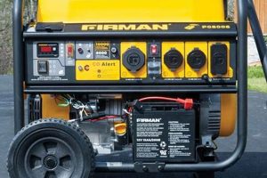
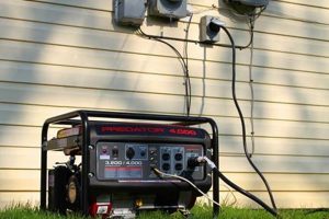
A schematic illustrating the connections for a typical six-wire ignition switch found on portable generators provides a crucial guide for installation, troubleshooting, and repair. This visual representation details how the switch interacts with the generator’s engine, battery, and other electrical components, specifying which wire connects to which terminal. A typical diagram will identify connections for functions such as the start circuit, run circuit, ignition coil, battery charging, and ground.
Understanding this interconnectedness is paramount for safe and effective generator operation. Correct wiring ensures the generator starts reliably, charges the battery appropriately, and shuts down as intended. Without a proper schematic, incorrect wiring can lead to malfunctions, damage to the generator’s electrical system, or even safety hazards. Historically, these diagrams have evolved alongside generator technology, reflecting the increasing complexity of modern units. Early generators had simpler wiring schemes, but contemporary models, with features like electric start and multiple power outlets, necessitate more intricate wiring arrangements.
The following sections delve into specific aspects of portable generator electrical systems, including detailed explanations of typical six-wire switch configurations, common troubleshooting scenarios, and best practices for safe wiring procedures.
Tips for Working with Generator Ignition Switches
Careful attention to detail is crucial when working with generator ignition systems. These tips offer guidance for safe and effective wiring practices.
Tip 1: Consult the Manufacturer’s Documentation: Always refer to the specific wiring diagram provided by the generator manufacturer. Generic diagrams may not accurately reflect the wiring configuration of a particular model.
Tip 2: Disconnect the Battery: Before performing any work on the ignition system, disconnect the negative battery cable to prevent accidental shorts and potential injury.
Tip 3: Use Correct Wire Gauge: Employing wires of inadequate gauge can lead to overheating and potential fire hazards. Select wire sizes appropriate for the current draw of each circuit, as specified in the generator’s documentation.
Tip 4: Secure Connections: Ensure all wire connections are clean, tight, and properly insulated to prevent intermittent operation or shorts. Use appropriate connectors and crimpers for reliable connections.
Tip 5: Protect Wiring from Damage: Route wiring away from hot engine components and moving parts to prevent chafing, melting, or other damage that could compromise the electrical system.
Tip 6: Test Functionality: After completing any wiring work, thoroughly test the generator’s operation to ensure the ignition switch functions correctly in all positions, including starting, running, and stopping the engine.
Tip 7: Seek Professional Assistance: If uncertainties arise regarding the wiring diagram or any aspect of the electrical system, consult a qualified electrician or generator technician for assistance.
Adherence to these precautions ensures the safe and reliable operation of the generator, minimizing the risk of electrical malfunctions and extending the lifespan of the equipment.
By understanding these key aspects of generator ignition systems, users can confidently maintain and troubleshoot their equipment, ensuring reliable power generation when needed.
1. Safety
Safe operation of a portable generator hinges critically on the correct interpretation and application of its ignition switch wiring diagram. Miswiring presents substantial risks, including electrocution, fire, and damage to the generator itself. Understanding the diagram is not merely a recommended practice; it is a fundamental safety requirement.
- Shock Hazard Prevention
Correct grounding, as indicated in the wiring diagram, is crucial for preventing electric shock. A properly grounded system directs fault currents safely to the earth, protecting users from potentially lethal shocks. Without proper grounding, the generator’s frame can become energized, posing a severe hazard. The diagram precisely indicates the grounding wire’s connection point, ensuring this essential safety feature functions correctly.
- Fire Hazard Mitigation
Overloading circuits, often caused by incorrect wiring, can generate excessive heat, leading to melted insulation and potential fires. The wiring diagram specifies the appropriate wire gauge for each circuit, ensuring they can handle the intended current load. Adhering to these specifications mitigates the risk of overheating and subsequent fire hazards.
- Equipment Protection
Incorrect wiring can damage sensitive electronic components within the generator, leading to malfunctions and costly repairs. The diagram guides users in connecting the ignition switch to the various components, such as the ignition coil and battery charging system, in the correct sequence and polarity. This ensures the proper voltage and current flow, protecting these components from damage.
- Carbon Monoxide Poisoning Prevention
While not directly related to the wiring diagram, the diagram facilitates the correct installation of the generator, which is crucial for preventing carbon monoxide poisoning. Proper installation includes adequate ventilation and placement away from enclosed spaces. A correctly functioning generator, enabled by proper wiring as per the diagram, reduces the risk of malfunctions that could lead to increased carbon monoxide emissions.
These safety facets underscore the critical importance of the wiring diagram. It serves as the blueprint for safe generator operation, guiding users in establishing a secure electrical system that protects both individuals and the equipment itself. Ignoring or misinterpreting the diagram compromises these safety measures, creating potentially hazardous operating conditions.
2. Functionality
Generator functionality relies directly on the accurate interpretation and implementation of the six-wire ignition switch wiring diagram. This diagram serves as the roadmap for controlling the generator’s engine, dictating how the start, run, and stop functions operate. Each of the six wires plays a specific role in this process, and their correct connection is paramount for achieving the desired functionality.
The “start” wire, for instance, energizes the starter motor, initiating the engine cranking process. Without its correct connection, as specified in the diagram, the generator will fail to start. Similarly, the “run” wire provides continuous power to the ignition system once the engine is running. A misconnection here could lead to the engine stalling after starting. The remaining wires contribute to essential functions such as battery charging and ground fault protection. Consider a scenario where the battery charging wire is incorrectly connected. This could result in a depleted battery, rendering the electric start system inoperable. Another example involves the ground wire: its proper connection is crucial for operator safety, preventing electric shock. Each wire’s role, meticulously detailed in the diagram, contributes to the overall system functionality. These examples highlight the direct cause-and-effect relationship between the wiring diagram and the generator’s ability to perform its intended function.
In conclusion, the six-wire ignition switch wiring diagram is not merely a technical reference; it is the key to unlocking the generator’s full operational potential. Its correct application ensures reliable starting, consistent running, and safe operation, fulfilling the generator’s fundamental purpose of providing power. Challenges arise when this crucial diagram is overlooked or misinterpreted, leading to functional failures and potential safety hazards. A deep understanding of the diagram empowers users to maintain and troubleshoot their generators effectively, guaranteeing reliable performance when power is most needed. This understanding extends beyond basic operation to encompass the safe and efficient utilization of the generator, contributing to its longevity and optimal performance.
3. Wiring Schematic
A wiring schematic is the cornerstone of understanding and interacting with a portable generator’s electrical system, particularly its six-wire ignition switch. This visual representation provides a detailed map of the electrical connections, crucial for proper installation, troubleshooting, and maintenance. Without a clear understanding of this schematic, the risks of malfunction, damage, and safety hazards increase significantly.
- Component Identification
The schematic clearly identifies each component within the ignition system, including the ignition switch, starter motor, ignition coil, battery, and various safety devices. This clear identification allows for targeted troubleshooting. For example, if the starter motor fails to engage, the schematic guides the user to the specific wiring related to that component, enabling efficient diagnosis and repair.
- Connection Clarity
The schematic illustrates the precise connection points for each wire emanating from the six-wire ignition switch. This clarity is essential for avoiding miswiring, which could lead to serious consequences. For example, connecting the “start” wire to the incorrect terminal could prevent the engine from starting or even cause damage to the electrical system.
- Safety Assurance
The schematic plays a vital role in ensuring the safe operation of the generator. It highlights critical safety features such as grounding and overcurrent protection. By following the schematic, users can ensure these safety mechanisms are correctly implemented, minimizing the risk of electrical shock or fire. For instance, the schematic indicates the correct connection point for the ground wire, which is crucial for preventing electrical shock.
- Troubleshooting Guidance
When malfunctions occur, the schematic serves as an invaluable troubleshooting tool. By tracing the wiring paths illustrated in the diagram, users can identify potential problems such as broken connections, faulty switches, or damaged components. For example, if the generator fails to charge the battery, the schematic can guide the user in checking the connections and components related to the charging circuit.
In essence, the wiring schematic acts as the Rosetta Stone for deciphering the complexities of a portable generator’s six-wire ignition switch. It empowers users with the knowledge needed to install, maintain, and troubleshoot the electrical system safely and effectively. Ignoring or misinterpreting the schematic compromises safety and functionality, potentially leading to costly repairs or even hazardous situations. Mastery of this document is therefore essential for anyone working with these power generation devices.
4. Color-Coded Wires
Color-coded wires within a portable generator’s six-wire ignition switch system are crucial for safe and accurate wiring. These color codes provide a visual language that simplifies the complex process of connecting the various components, minimizing the risk of errors and ensuring proper functionality. Understanding this color-coding scheme is essential for anyone working with these systems.
- Simplified Installation and Maintenance
Color-coding significantly simplifies the process of connecting the ignition switch to the generator’s electrical system. By matching the wire colors to the corresponding terminals on the switch and other components, users can quickly and accurately complete the wiring process, even without extensive electrical experience. This ease of connection also translates to simpler maintenance and troubleshooting.
- Reduced Risk of Miswiring
The standardized color codes minimize the risk of miswiring, a critical factor in preventing malfunctions and safety hazards. Each wire’s designated color corresponds to a specific function within the ignition system. For example, the black wire typically represents the ground connection, while the red wire often signifies the power source. This clear designation reduces the chance of accidentally connecting a wire to the wrong terminal, which could lead to damage to the generator or even pose a risk of electric shock.
- Enhanced Troubleshooting Efficiency
In the event of a malfunction, the color-coded wires assist in troubleshooting by allowing for quick identification of the various circuits. This visual aid speeds up the diagnostic process, enabling faster identification and resolution of electrical issues. For example, if the generator fails to start, a technician can quickly trace the red wire to ensure the power source is correctly connected.
- Universal Standardization
While specific color assignments may vary slightly between manufacturers, a general degree of standardization exists within the industry. This standardization allows for greater interoperability and simplifies the process of working with different generator models. For instance, the black wire almost universally denotes the ground connection, regardless of the specific generator brand. This consistency provides a familiar framework for technicians and users, simplifying maintenance and repair tasks across various generator models.
In summary, color-coded wires play a pivotal role in simplifying the complexities of portable generator wiring. They facilitate correct connections, reduce errors, and enhance troubleshooting efficiency. This color-coding system is integral to the overall safety and functionality of the generator, enabling users to confidently operate and maintain their equipment. Understanding and adhering to these color codes is therefore essential for anyone interacting with a portable generators six-wire ignition switch system.
5. Switch Positions (ON/OFF/START)
Understanding the function of each switch position (ON/OFF/START) on a portable generator’s six-wire ignition switch is crucial for safe and effective operation. The wiring diagram provides the blueprint for these functions, detailing how each position interacts with the generator’s electrical system. Correct operation of the switch ensures proper engine starting, running, and shutdown procedures, preventing damage and potential hazards.
- OFF Position
The OFF position completely disconnects the generator’s electrical system, ensuring no power flows to any circuits. This is essential for safe maintenance and prevents accidental starting. The wiring diagram specifies which circuits are opened in this position, guaranteeing complete electrical isolation. This safeguards users from electrical shock during maintenance and prevents unintended engine operation.
- START Position
The START position engages the starter motor, cranking the engine to initiate combustion. The wiring diagram dictates how the switch routes power to the starter solenoid in this position. This connection energizes the solenoid, engaging the starter motor and cranking the engine. Once the engine starts, the switch must be released to the ON position. Holding the switch in the START position for extended periods can damage the starter motor.
- ON Position
The ON position provides continuous power to the ignition system and other essential circuits, allowing the engine to run. The wiring diagram illustrates how this position connects the generator’s power source to the necessary circuits, ensuring sustained operation. This uninterrupted power flow enables the generator to produce electricity. This position also activates the battery charging circuit, replenishing the battery while the generator runs.
- Understanding the Interplay
The interplay between these switch positions, as defined by the wiring diagram, forms the foundation of the generator’s operation. Each position serves a distinct purpose, and their correct utilization is essential for safe and efficient power generation. Attempting to start the generator with the switch in the ON position, for instance, can damage the electrical system. Similarly, leaving the switch in the START position after the engine starts can damage the starter motor. The wiring diagram clarifies these interactions, guiding users in the proper operation of the ignition switch and ensuring the generator’s longevity and safe functionality.
In conclusion, the relationship between the switch positions and the six-wire ignition switch wiring diagram is fundamental to understanding and operating a portable generator. The diagram serves as the guide for how each switch position interacts with the generator’s electrical components, ensuring proper starting, running, and shutdown procedures. This understanding is critical not only for efficient power generation but also for the safe and prolonged lifespan of the equipment.
6. Troubleshooting
Troubleshooting a portable generator’s electrical system relies heavily on a thorough understanding of the six-wire ignition switch wiring diagram. This diagram serves as the primary diagnostic tool, guiding users through the process of identifying and resolving electrical faults. A systematic approach, coupled with accurate diagram interpretation, allows for efficient and effective troubleshooting.
The cause-and-effect relationship between specific wiring configurations and observed symptoms becomes apparent when referencing the diagram. For example, if the generator fails to start, the diagram allows one to trace the starting circuit, identifying potential points of failure such as a faulty ignition switch, a disconnected wire, or a malfunctioning starter solenoid. Similarly, issues with battery charging can be diagnosed by examining the charging circuit depicted in the diagram, pinpointing potential problems like a broken charging wire or a faulty voltage regulator. The diagram’s value extends beyond simple component identification; it provides insight into the interconnectedness of the system, allowing for a more comprehensive diagnostic approach. For instance, a seemingly unrelated symptom like flickering lights could be traced back to a faulty ground connection, as revealed by the diagram.
Practical applications of this understanding are numerous. Consider a scenario where a generator unexpectedly shuts down during operation. By consulting the wiring diagram, one might trace the problem to a loose connection in the run circuit, a faulty ignition coil, or even a malfunctioning safety device. The diagram empowers users to systematically eliminate potential causes, leading to a swift resolution. Furthermore, an understanding of the diagram facilitates preventative maintenance. By periodically inspecting the wiring and connections as depicted in the diagram, one can identify potential issues before they escalate into major malfunctions. This proactive approach minimizes downtime and extends the generator’s operational lifespan. Mastery of the six-wire ignition switch wiring diagram transforms troubleshooting from a daunting task into a systematic process, ensuring efficient repairs and reliable generator performance. This knowledge contributes significantly to the safe and effective utilization of portable generators, minimizing downtime and maximizing their operational lifespan.
Frequently Asked Questions
This section addresses common inquiries regarding six-wire ignition switch wiring diagrams for portable generators. Clarity on these points is essential for safe and effective generator operation.
Question 1: Where can one locate a specific wiring diagram for a particular generator model?
The generator’s owner’s manual is the primary source for model-specific wiring diagrams. Manufacturer websites often provide manuals for download if the physical copy is unavailable. Contacting the manufacturer directly may also be necessary in some cases.
Question 2: What are the potential risks of using a generic wiring diagram instead of the manufacturer’s specified diagram?
Using a generic diagram can lead to incorrect wiring, potentially resulting in generator malfunction, electrical hazards, and damage to the unit. Always prioritize the manufacturer’s diagram for accurate wiring information.
Question 3: What does each of the six wires typically represent in a standard six-wire ignition switch setup?
While specific color codes may vary, common functions include: battery positive, start circuit, run circuit, ignition coil, ground, and accessories. The manufacturer’s diagram provides definitive identification for each wire’s function.
Question 4: How can one determine the correct wire gauge to use for each connection?
The generator’s owner’s manual specifies the correct wire gauge for each circuit. Using an inadequate gauge can lead to overheating and potential fire hazards. Consult a qualified electrician if any uncertainty exists.
Question 5: What steps should be taken if the generator fails to start, even after verifying correct wiring according to the diagram?
Systematic troubleshooting is necessary. Check for fuel, ensure the spark plug is functioning correctly, and inspect the air filter. If the problem persists, consult a qualified technician for further diagnosis.
Question 6: How often should the wiring and connections be inspected for damage or wear?
Regular visual inspections are recommended, ideally before each use and more thoroughly at least annually. Look for signs of wear, damage, or loose connections. Promptly address any identified issues to prevent malfunctions and ensure safe operation.
Careful attention to these frequently asked questions, coupled with a thorough understanding of the generator’s wiring diagram, promotes safe and effective operation, minimizes potential hazards, and contributes to the longevity of the equipment.
The next section offers practical tips for working with generator ignition switches, providing further guidance for safe and effective operation.
Conclusion
Mastery of portable generator six-wire ignition switch wiring diagrams is paramount for safe and reliable operation. This document provides the essential roadmap for understanding the complex electrical interconnections within these power generation devices. Accurate interpretation of the diagram ensures correct installation, enabling key functions like starting, running, and safely shutting down the generator. Furthermore, the diagram serves as an invaluable troubleshooting tool, guiding users through the process of diagnosing and resolving electrical faults. Color-coded wires, deciphered through the diagram, simplify connections and minimize errors. A clear understanding of the ON/OFF/START switch positions, as detailed in the diagram, dictates proper engine control and prevents potential damage.
Emphasis on the critical importance of consulting the manufacturer’s specific diagram for each generator model cannot be overstated. Generic diagrams pose significant risks of miswiring, leading to malfunctions and potential safety hazards. Investing time in understanding the specific diagram for one’s generator is an investment in safety and operational efficiency. This knowledge empowers users to maintain and troubleshoot their equipment effectively, ensuring reliable power generation when needed most. Prioritizing proper wiring practices, guided by the manufacturer’s diagram, ensures not only the longevity of the equipment but also the safety of those operating and relying upon it.


