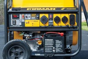
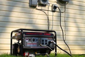
Connecting a portable generator to a home’s electrical system safely and effectively requires a transfer switch. This device allows the generator to power essential circuits while isolating them from the utility grid, preventing dangerous backfeeding. A typical installation involves connecting the generator to the transfer switch inlet, then wiring the switch to selected circuits within the electrical panel. This configuration ensures that power flows correctly and safeguards both the generator and the broader electrical infrastructure.
Safe generator integration is crucial for protecting appliances and utility workers during power outages. A properly installed transfer switch prevents damage from voltage fluctuations and eliminates the risk of electrocution for line workers. Historically, direct generator connections to appliances were common, posing significant safety hazards. Transfer switches have become essential safety devices, enabling reliable backup power without compromising the integrity of the electrical grid.
The following sections will detail the necessary steps, safety precautions, and code requirements for correctly installing a transfer switch for a portable generator, covering topics such as selecting the appropriate switch, preparing the electrical panel, making the necessary connections, and testing the system.
Tips for Transfer Switch Wiring
Safe and effective transfer switch installation requires careful planning and execution. These tips provide essential guidance for a successful project.
Tip 1: Consult Local Electrical Codes: Adherence to local electrical codes and permitting requirements is paramount for safety and legality. Regulations vary by jurisdiction, so professional consultation is recommended.
Tip 2: Choose the Right Transfer Switch: Select a transfer switch rated for the generator’s wattage and the load of the chosen circuits. Consider future needs and potential expansion.
Tip 3: Prioritize Essential Circuits: Identify essential circuits for backup power, such as refrigeration, heating, and lighting. Avoid overloading the generator by carefully calculating wattage requirements.
Tip 4: Disconnect Main Power: Before working on the electrical panel, disconnect the main power supply to prevent electrical shock. Verify disconnection with a voltage tester.
Tip 5: Proper Grounding is Crucial: Ensure the generator and transfer switch are properly grounded to prevent electrical hazards and ensure safe operation.
Tip 6: Use Appropriate Wiring and Conduit: Select appropriately sized wiring and conduit based on the amperage requirements. Secure wiring neatly within the panel and protect it from damage.
Tip 7: Double-Check Connections: Carefully verify all connections before energizing the system. Loose connections can cause overheating, malfunction, or even fire.
Tip 8: Test the System Thoroughly: After installation, test the transfer switch and generator to ensure proper operation. Simulate a power outage to confirm the system functions as expected.
Following these tips contributes significantly to a safe and functional transfer switch installation, enabling reliable backup power during outages.
This comprehensive approach ensures not only functionality but also the long-term safety and reliability of the electrical system.
1. Power Off
Deactivating the main power supply before initiating any work on a transfer switch installation is paramount for electrical safety. This critical step eliminates the risk of electrical shock, a potentially fatal hazard. Working on energized circuits exposes individuals to dangerous voltages, potentially leading to severe injury or death. Disconnecting power ensures a safe working environment, allowing for focused and risk-free wiring procedures. For instance, before connecting the transfer switch to the electrical panel, the main breaker must be switched off and verified with a voltage tester. This confirms the absence of live current and establishes a safe environment for the subsequent wiring steps.
Beyond personal safety, deactivating power protects sensitive electronic components within the transfer switch and connected circuits. Electrical surges or unintentional short circuits during the wiring process can damage these components, resulting in malfunction or complete failure. By ensuring the system is de-energized, the risk of such damage is mitigated, preserving the integrity of the equipment. Consider a scenario where a wire is accidentally brushed against a live terminal. The resulting surge could damage sensitive electronics within the transfer switch, potentially rendering it unusable.
Power disconnection serves as the foundational safety precaution for transfer switch installation. This critical step protects both personnel and equipment from electrical hazards. Failure to adhere to this fundamental principle can have dire consequences, underscoring its critical role in the process. Neglecting power disconnection renders the entire operation unsafe, significantly increasing the risk of accidents and equipment damage. Establishing a safe working environment through power deactivation allows for methodical and error-free wiring, ensuring a successful and hazard-free installation.
2. Correct Gauge Wiring
Appropriate wire gauge selection is crucial for safe and efficient transfer switch installation. Undersized wiring poses significant fire hazards due to overheating, while oversized wiring adds unnecessary cost. Correct gauge ensures efficient power delivery from the generator to the connected circuits without compromising safety.
- Ampacity and Load Calculation:
Wire gauge selection hinges on the amperage capacity of the wire (ampacity) and the anticipated load of the connected circuits. The wire must handle the maximum current draw without overheating. Calculating the total wattage of the intended loads and dividing by the generator’s voltage yields the required amperage. Consulting an ampacity chart then determines the appropriate wire gauge. For example, a 15-amp circuit powering essential lights and a refrigerator might require 14-gauge wire, while a 20-amp circuit for a well pump might necessitate 12-gauge wire. Incorrect ampacity calculation leads to either undersized wiring, creating fire hazards, or oversized wiring, incurring unnecessary expenses.
- Wire Material and Insulation:
Copper wiring is standard for residential applications due to its superior conductivity. Aluminum wiring, while less expensive, requires larger gauges for the same ampacity and presents specific connection challenges. Insulation type is also crucial, with THHN being common for interior wiring due to its heat resistance. Using incorrect wire material or insulation can compromise safety and longevity. For instance, using aluminum wiring with connections designed for copper can lead to overheating and potential fire hazards. Similarly, using insulation not rated for the intended environment could result in premature degradation and safety risks.
- Distance and Voltage Drop:
Longer wire runs can experience voltage drop, reducing the effective power delivered to the appliances. While negligible for short distances, voltage drop becomes significant over longer runs, particularly with higher loads. Increasing the wire gauge can mitigate voltage drop, ensuring appliances receive adequate power. For example, a long run to a well pump might require a larger gauge wire than a shorter run to a lighting circuit, even if the amperage requirements are similar. Neglecting voltage drop can lead to appliance malfunction and reduced efficiency.
- Code Compliance and Safety Standards:
Adhering to local electrical codes and national safety standards is mandatory for transfer switch wiring. Codes dictate specific wire types, gauges, and installation methods for safety and compliance. Ignoring these regulations can lead to inspection failures, safety hazards, and potential legal liabilities. For example, using Romex cable within a conduit might violate local codes, necessitating costly rework. Compliance with code requirements not only ensures safety but also safeguards against potential legal repercussions.
Selecting the correct wire gauge is an integral component of a safe and functional transfer switch installation. Careful consideration of load requirements, wire material, distance, and code compliance ensures efficient and safe power delivery from the generator to essential circuits during outages. Overlooking these factors compromises safety, increases costs, and potentially leads to equipment damage or failure. By adhering to these principles, the installation achieves optimal performance, reliability, and safety, providing essential power during critical situations.
3. Secure Connections
Reliable operation of a portable generator transfer switch hinges on secure electrical connections. Loose or improperly made connections can lead to overheating, arcing, and potential fire hazards. Ensuring tight, well-made connections throughout the installation is crucial for safety and functionality.
- Tightened Terminals:
All terminal screws on the transfer switch, generator inlet, and within the electrical panel must be firmly tightened to the manufacturer’s specifications. Loose connections create resistance, generating heat and potentially causing fires. Using a torque screwdriver helps achieve consistent and appropriate tightness. For instance, a loose connection on a heavily loaded circuit can quickly overheat, potentially igniting surrounding insulation and causing a fire. A torque screwdriver ensures consistent and appropriate tightening, minimizing this risk.
- Clean Contact Surfaces:
Clean contact surfaces are essential for optimal conductivity and secure connections. Corrosion or debris on the wires or terminals can impede current flow and create hot spots. Using a wire brush or emery cloth to clean surfaces before making connections ensures optimal contact and minimizes resistance. For example, a corroded wire connected to a transfer switch terminal can create significant resistance, leading to heat buildup and potential failure. Thorough cleaning of contact surfaces mitigates this risk.
- Proper Crimping and Connectors:
When using crimp connectors, proper crimping technique and appropriate connector selection are crucial for secure connections. Incorrect crimping can result in loose strands, increasing resistance and creating potential failure points. Using the correct crimping tool and connector size ensures a tight, reliable connection. For instance, using a poorly crimped connector on a generator’s output cable can lead to intermittent power delivery or complete failure during an outage. Proper crimping techniques ensure a secure and reliable connection.
- Strain Relief and Secure Wiring:
Strain relief prevents wires from pulling loose from their connections, particularly in areas subject to vibration or movement, such as the generator connection. Securing wires with appropriate clamps or cable ties maintains tidy wiring and prevents accidental disconnections. For example, without proper strain relief, the vibration from a running generator can gradually loosen the connection at the transfer switch inlet, eventually leading to a power interruption. Securing the cables prevents such disruptions.
Secure connections are fundamental to a safe and reliable transfer switch installation. By ensuring tight terminals, clean contact surfaces, proper crimping techniques, and adequate strain relief, the entire system operates safely and effectively, providing reliable backup power when needed. Neglecting these aspects can compromise safety, create potential fire hazards, and lead to system failure during critical outages. Meticulous attention to these connection details ensures long-term reliability and peace of mind during power disruptions.
4. Proper Grounding
Effective grounding is paramount for safe and reliable portable generator transfer switch operation. A proper grounding system safeguards against electrical shocks and equipment damage by providing a low-resistance path for fault currents to flow back to the source. This critical safety measure protects individuals and equipment from potentially hazardous voltage surges and ensures the intended operation of overcurrent protection devices.
- Shock Prevention:
Grounding protects individuals from electrical shocks by providing a low-impedance path for fault currents to flow to ground, rather than through a person’s body. If a live wire contacts a grounded metal surface, the fault current rapidly trips the circuit breaker, minimizing the duration of potential shock exposure. Without proper grounding, a faulty appliance could energize its metal casing, posing a lethal threat to anyone touching it. A grounded system rapidly diverts the fault current, minimizing the risk of injury.
- Equipment Protection:
Grounding safeguards sensitive electronic equipment connected to the generator by providing a path for surge currents to dissipate harmlessly. Lightning strikes or power surges can induce high voltages in electrical systems. A proper ground connection allows these surges to flow to earth, protecting sensitive electronics from damage. For instance, a lightning strike near a power line can induce a voltage surge that could damage connected appliances. A properly grounded system diverts this surge to earth, protecting the equipment.
- Overcurrent Protection Device Operation:
Effective grounding ensures the proper operation of overcurrent protection devices, such as circuit breakers and fuses. During a ground fault, the grounding system provides a low-resistance path for fault current to flow, allowing the overcurrent device to quickly detect and interrupt the fault. Without a proper ground, the fault current may not be sufficient to trip the breaker, leading to sustained overheating and potential fire hazards. A solid grounding system ensures these devices function as designed, protecting the electrical system from damage.
- Generator Grounding:
The generator itself must be properly grounded. This involves connecting a grounding wire from the generator’s grounding terminal to a grounding electrode, such as a grounding rod driven into the earth. This connection provides a path for fault currents from the generator to dissipate safely, preventing the generator frame from becoming energized. Without proper generator grounding, a fault within the generator could energize its frame, creating a shock hazard.
Proper grounding is integral to a safe and functional portable generator transfer switch installation. By providing a low-resistance path for fault currents, grounding protects individuals from electrical shock, safeguards equipment from damage, and ensures the reliable operation of overcurrent protection devices. Neglecting grounding compromises safety and increases the risk of serious incidents. A well-grounded system is essential for reliable and safe operation during power outages.
5. Code Compliance
Adherence to relevant electrical codes is paramount when installing a portable generator transfer switch. Codes, such as the National Electrical Code (NEC) in the United States, provide specific guidelines and regulations designed to ensure safety and prevent electrical hazards. These codes dictate appropriate wiring methods, conductor sizes, overcurrent protection, grounding procedures, and transfer switch installation requirements. Ignoring these codes compromises safety and can lead to serious consequences, including fire hazards, equipment damage, and even fatalities. For instance, using an improperly sized conductor can lead to overheating and fire, while inadequate grounding can create a shock hazard. Code compliance ensures the installation meets established safety standards, protecting both individuals and property.
Connecting a portable generator to a home’s electrical system without a properly installed and code-compliant transfer switch can lead to backfeeding, a dangerous phenomenon where electricity flows from the generator back into the utility grid. This poses a significant threat to utility workers who may be unaware of the energized lines, assuming they are de-energized during an outage. Backfeeding can result in serious injury or death. Furthermore, incorrect wiring can damage the generator and connected appliances. For example, failing to isolate the generator’s neutral from the utility neutral can create a ground loop, resulting in equipment damage and potential safety hazards. Code compliance ensures the transfer switch isolates the generator’s power from the utility grid, preventing backfeeding and protecting both utility workers and equipment.
Code compliance is not merely a bureaucratic hurdle but a critical aspect of safe and effective transfer switch installation. Adhering to established codes ensures the system operates safely and reliably, protecting individuals and property from electrical hazards. Ignoring these regulations compromises safety and can have severe repercussions. Furthermore, code compliance often involves obtaining permits and inspections, providing an additional layer of oversight and ensuring the installation meets established safety standards. Consulting qualified electricians and obtaining necessary permits demonstrates a commitment to safety and ensures the installation adheres to all applicable regulations. This not only protects individuals and property but also ensures the long-term reliability and safety of the electrical system.
6. Thorough Testing
Thorough testing forms an indispensable final stage in the safe and effective installation of a portable generator transfer switch. Testing validates the integrity of the wiring, confirms proper transfer switch operation, and ensures the system functions as intended during an actual power outage. Neglecting this crucial step risks equipment damage, potential hazards, and ultimately, the failure of the backup power system when needed most. Testing verifies that the transfer switch correctly isolates the home’s circuits from the utility grid when the generator is operating, preventing dangerous backfeeding. It also confirms that the selected circuits receive power from the generator and that the system operates within safe electrical parameters.
A comprehensive testing procedure should include simulating a power outage by disconnecting the main power supply and activating the generator. This allows observation of the transfer switch’s automatic or manual transition to generator power. Each connected circuit should be individually tested to ensure it receives power from the generator. Furthermore, the system should be tested under various load conditions to ensure it can handle the anticipated power demands. For example, if the well pump, refrigerator, and several lights are intended to run simultaneously, the test should include running all these loads concurrently to confirm the system’s capacity and stability. Monitoring voltage and amperage during the test verifies the system operates within safe limits. Discovering and rectifying any issues during testing, such as incorrect wiring or inadequate generator capacity, prevents potential problems during an actual outage.
Thorough testing provides essential validation of the entire installation process. It confirms the safety and functionality of the system, providing assurance of reliable backup power during outages. Identifying and addressing potential problems during testing mitigates risks and ensures the system performs as expected when needed. This proactive approach not only safeguards equipment and personnel but also provides peace of mind knowing the backup power system will function reliably during critical situations. A properly tested system forms the cornerstone of a robust and reliable emergency power solution.
Frequently Asked Questions
Addressing common inquiries regarding portable generator transfer switch installations helps clarify potential uncertainties and ensures safe and effective implementation.
Question 1: Is professional installation required for a transfer switch?
While technically feasible for experienced individuals, professional installation is strongly recommended. Electrical work involves inherent risks, and incorrect wiring can lead to hazardous situations. Licensed electricians possess the expertise to ensure code compliance and safe operation.
Question 2: What size transfer switch is needed for a specific generator?
Transfer switch size depends on the generator’s wattage output. The switch must be rated to handle the maximum power the generator can supply. Overloading a transfer switch can lead to overheating and potential fire hazards.
Question 3: Can any circuit be connected to a transfer switch?
Not all circuits are suitable for generator power. Prioritize essential circuits like refrigerators, heating systems, and lighting. Avoid connecting non-essential loads to prevent overloading the generator. Careful load calculation is essential to avoid exceeding the generator’s capacity.
Question 4: What type of wiring is recommended for transfer switch installations?
Copper wiring with appropriate insulation, such as THHN, is generally recommended for its conductivity and heat resistance. The wire gauge must be selected based on the amperage requirements of the connected circuits, adhering to local electrical codes and ampacity charts.
Question 5: How is a transfer switch grounded?
Proper grounding is critical for safety. The transfer switch should be connected to the main electrical panel’s grounding system, ensuring a low-resistance path for fault currents. The generator also requires proper grounding, typically through a grounding rod driven into the earth.
Question 6: How often should a transfer switch be tested?
Regular testing, ideally every few months, ensures the system functions correctly. Simulate a power outage by disconnecting the main power and activating the generator. Verify that the transfer switch operates as expected and that all intended circuits receive power.
Careful consideration of these frequently asked questions, combined with adherence to local electrical codes and professional guidance, ensures a safe and effective transfer switch installation. This proactive approach safeguards against potential hazards and guarantees reliable backup power during critical situations.
For further inquiries or specific guidance regarding local regulations and installation procedures, consulting a qualified electrician is highly recommended.
Conclusion
Safe and reliable backup power during outages hinges on the correct installation of a portable generator transfer switch. This comprehensive exploration has detailed the critical aspects of this process, emphasizing the significance of proper wiring techniques, adherence to electrical codes, and thorough system testing. Key takeaways include prioritizing safety through power disconnection, selecting appropriate wire gauges, ensuring secure connections, establishing robust grounding systems, and complying with all applicable regulations. Each of these elements plays a vital role in ensuring the system’s effectiveness and preventing potential hazards.
Reliable backup power provides not just convenience but also essential support for critical systems during emergencies. Investing time and effort in proper transfer switch installation safeguards both life and property. Thorough planning, meticulous execution, and adherence to established safety standards ensure a robust and dependable backup power solution, providing peace of mind during unforeseen power disruptions. Professional consultation remains advisable for addressing specific circumstances and ensuring full compliance with local regulations.

