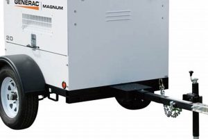
A schematic representation of the electrical connections within a specific brand of portable power generation equipment illustrates how components like the alternator, outlets, control panel, and engine interface are interconnected. This visual guide aids in understanding the flow of electricity within the unit, crucial for troubleshooting, repairs, and modifications.
Access to accurate electrical schematics is essential for maintaining the safe and effective operation of portable generators. Understanding these diagrams allows users to diagnose faults, replace damaged components correctly, and potentially expand the unit’s capabilities. Correct wiring ensures proper grounding, preventing electrical shocks and protecting connected devices. Historically, these diagrams were primarily paper-based, but digital versions now offer increased accessibility and clarity.
This article will further explore the key components commonly found in these electrical layouts, including the alternators wiring configuration, outlet wiring specifications, and the connections to vital safety features such as circuit breakers and ground fault interrupters. It will also delve into the practical application of these schematics for common maintenance and repair scenarios.
Tips for Working with Portable Generator Wiring Diagrams
Careful attention to electrical schematics is paramount for safe and effective generator operation. The following tips offer guidance for interpreting and utilizing these diagrams.
Tip 1: Safety First: Always disconnect the generator from all power sources before accessing any internal wiring. This includes disconnecting the spark plug wire to prevent accidental starting.
Tip 2: Locate the Correct Diagram: Ensure the diagram matches the specific generator model and serial number. Using an incorrect diagram can lead to miswiring and potential damage.
Tip 3: Understand the Symbols: Familiarize oneself with standard electrical symbols used in schematics. These represent various components like resistors, capacitors, and switches.
Tip 4: Trace the Circuit: Follow the flow of electricity through the diagram to understand how different components interact. This is crucial for diagnosing faults and understanding functionality.
Tip 5: Use Proper Tools and Techniques: Employ appropriate tools for any wiring work, including insulated screwdrivers and wire strippers. Ensure connections are secure and correctly insulated.
Tip 6: Consult Qualified Professionals: If uncertainties arise or complex repairs are required, consult a qualified electrician or authorized service center. Incorrect wiring can create safety hazards and damage the generator.
Tip 7: Document Changes: If modifications are made, document them clearly on the diagram or in a separate log. This will prove invaluable for future troubleshooting and maintenance.
Adhering to these precautions and utilizing the information within the wiring diagram contributes significantly to the safe, efficient, and long-lasting operation of the equipment.
By following these tips, one can confidently utilize wiring diagrams for troubleshooting, maintenance, and modifications, ultimately ensuring the reliable performance and longevity of the generator.
1. Safety Precautions
Safety is paramount when working with electrical equipment, and portable generators are no exception. Understanding the wiring diagram is inextricably linked to safe operation, maintenance, and repair. The diagram provides crucial information for mitigating potential hazards and ensuring proper grounding, connection, and component interaction. Neglecting safety precautions can lead to serious injury, equipment damage, or fire.
- Disconnecting Power Sources:
Before consulting or working with a wiring diagram, disconnecting all power sources is essential. This includes not only unplugging the unit from any outlets but also disconnecting the spark plug wire to prevent accidental starting. This eliminates the risk of electric shock or unintended operation during maintenance or repairs.
- Proper Grounding:
The wiring diagram illustrates the grounding scheme, a critical safety feature. A correctly grounded generator protects users from electric shock and safeguards connected equipment from damage. The diagram guides proper grounding procedures, ensuring the system’s integrity and minimizing potential hazards.
- Correct Component Handling:
Wiring diagrams specify the location and function of various components. This information is crucial for safe handling and replacement. For example, understanding capacitor discharge procedures before handling them prevents potential electrical shocks. The diagram informs safe practices for each component, minimizing risks.
- Overload Prevention:
Wiring diagrams detail the generator’s electrical capacity and outlet configurations. This information is essential for preventing overloads, which can lead to overheating, fire, or damage to connected equipment. Adhering to the specified wattage limits ensures safe and reliable operation within the generator’s designed parameters.
These safety precautions, informed by the wiring diagram, are fundamental for safe and effective generator operation. Ignoring these guidelines can have serious consequences. Consulting the diagram before any interaction with the generator safeguards against potential hazards and ensures proper functionality, contributing to a secure operating environment.
2. Component Identification
Accurate component identification is fundamental to interpreting a Generac portable generator wiring diagram. The diagram serves as a roadmap, visually representing the generator’s internal components and their interconnections. Understanding the function and location of each element is crucial for effective troubleshooting, maintenance, and repairs. Without proper component identification, navigating the diagram and performing necessary tasks becomes significantly more challenging, potentially leading to incorrect diagnoses and unsafe practices.
- Alternator:
The alternator is the heart of the generator, responsible for converting mechanical energy into electrical power. The wiring diagram details its connections to the voltage regulator, outlets, and other crucial components. Recognizing the alternator’s representation on the diagram allows for diagnosing charging issues or output failures.
- Voltage Regulator:
This component maintains stable voltage output from the generator. The diagram illustrates its connection to the alternator and control panel, enabling troubleshooting of voltage fluctuations or unstable power delivery. Understanding its role within the circuitry facilitates accurate diagnosis and repair.
- Control Panel:
The control panel houses various switches, outlets, and indicators. The wiring diagram clarifies the connections between these elements and internal components. This knowledge assists in identifying the source of power disruptions or faulty indicators, enabling targeted repairs.
- Circuit Breakers and Fuses:
These protective devices prevent overloads and short circuits. The diagram pinpoints their location within the circuitry and illustrates their connection to specific outlets or components. This facilitates rapid identification and replacement of tripped breakers or blown fuses, restoring power safely.
Precise component identification, facilitated by a clear understanding of the Generac portable generator wiring diagram, empowers users to effectively diagnose and address electrical issues. This knowledge ensures safe and efficient maintenance, contributing to the generator’s longevity and reliable performance. Accurate identification prevents misdiagnosis and ensures appropriate repairs, mitigating potential safety risks and optimizing generator functionality.
3. Wire Color Codes
Wire color codes within a Generac portable generator wiring diagram are crucial for accurate circuit tracing, component identification, and safe maintenance. These codes provide a standardized visual language, simplifying complex electrical systems and facilitating effective troubleshooting. Each wire’s color corresponds to a specific function or connection, eliminating guesswork and reducing the risk of miswiring. This standardization is essential for ensuring proper operation and preventing potentially hazardous electrical faults.
For instance, the “hot” wire, often carrying 120V, is typically black or red. Neutral wires are commonly white or gray, providing a return path for the current. Green or bare copper wires designate the ground connection, crucial for safety. Understanding these color codes allows one to trace the flow of electricity through the generator, identify the purpose of each wire within a circuit, and make informed decisions during repairs or modifications. Ignoring or misinterpreting these codes can lead to incorrect connections, potentially damaging the generator or creating safety hazards.
Practical applications of this understanding include diagnosing faulty outlets, tracing the source of power interruptions, and correctly connecting new components. By following the color-coded wires within the diagram, one can systematically identify the source of a problem and implement the appropriate solution. This knowledge is essential for anyone working with a Generac portable generator, from homeowners performing basic maintenance to technicians conducting complex repairs. Mastery of wire color codes, combined with a comprehensive understanding of the wiring diagram, contributes significantly to the safe, efficient, and long-lasting operation of the generator.
4. Circuit Tracing
Circuit tracing within a Generac portable generator wiring diagram is a systematic process of following the flow of electricity through the unit’s various components. This process utilizes the diagram as a roadmap, allowing one to understand the interconnectedness of elements such as the alternator, voltage regulator, control panel, outlets, and safety features. Effective circuit tracing requires a clear understanding of standard electrical symbols, wire color codes, and component functions. The ability to trace circuits is essential for diagnosing malfunctions, isolating faulty components, and implementing effective repairs.
Consider a scenario where a specific outlet on the generator fails to provide power. Circuit tracing, guided by the wiring diagram, allows one to follow the electrical path from the alternator, through the circuit breaker, and ultimately to the affected outlet. This systematic approach can reveal a tripped breaker, a damaged wire, or a faulty outlet receptacle as the root cause. Without circuit tracing, the troubleshooting process becomes significantly more challenging, potentially leading to unnecessary component replacement or unresolved issues. Another example involves diagnosing a malfunctioning voltage regulator. Tracing the circuit related to the regulator allows for the identification of associated components and wiring, facilitating targeted testing and repair.
Mastery of circuit tracing, coupled with a comprehensive understanding of the Generac portable generator wiring diagram, empowers users to diagnose and address electrical issues effectively. This methodical approach minimizes downtime, reduces repair costs, and enhances safety by ensuring accurate fault identification and targeted repairs. The ability to trace circuits is a fundamental skill for anyone tasked with maintaining or repairing these complex electrical systems, contributing significantly to their safe and reliable operation.
5. Connector Locations
Connector locations play a vital role within a Generac portable generator wiring diagram. These diagrams depict the precise points where various electrical components connect, facilitating accurate assembly, disassembly, and troubleshooting. Understanding connector locations is crucial for safe and efficient maintenance, repair, and modification of the generator. The diagram acts as a guide, enabling technicians and users to identify each connector’s purpose, ensuring correct connections and preventing potentially hazardous miswiring.
For instance, the diagram specifies the connector for the alternator’s output, allowing for proper connection to the main power distribution system. Similarly, connector locations for the voltage regulator, control panel, and various safety features are clearly indicated. This precision enables targeted troubleshooting. If a specific circuit experiences a fault, the diagram guides technicians to the relevant connectors, allowing for efficient isolation and testing of individual components. This targeted approach minimizes downtime and reduces repair costs. Consider a scenario where a faulty voltage regulator needs replacement. The wiring diagram’s accurate depiction of connector locations enables swift and precise disconnection of the faulty component and subsequent connection of the replacement, minimizing disruption and ensuring correct operation. Furthermore, understanding connector locations is crucial for expanding the generator’s capabilities, such as adding additional outlets or integrating a transfer switch. The diagram provides the necessary information for safe and correct integration of new components, ensuring compatibility and preventing electrical conflicts.
Precise knowledge of connector locations, as detailed within the Generac portable generator wiring diagram, is paramount for safe and efficient interaction with the generator’s electrical system. This information streamlines maintenance, simplifies complex repairs, and facilitates safe modifications. Accurate connector identification prevents miswiring, protects components from damage, and ensures the generator’s reliable operation. This understanding underpins the effective use of the wiring diagram as a vital tool for maintaining and troubleshooting the generator’s electrical system.
6. Grounding Scheme
The grounding scheme within a Generac portable generator wiring diagram is a critical safety feature designed to prevent electrical shock and protect connected equipment. This scheme directs fault currents safely into the earth, minimizing the risk of injury or damage. The wiring diagram explicitly details the grounding connections, typically illustrating a dedicated ground wire connecting the generator’s frame and specific points within the electrical system to a grounding rod or electrode. This deliberate pathway ensures that any unintentional contact with a live wire results in a rapid diversion of current, minimizing the duration and severity of potential shock. Furthermore, the grounding system protects connected devices from damage caused by voltage surges or imbalances by providing a low-resistance path for excess current.
A practical example of the grounding scheme’s importance involves operating the generator in wet conditions. Moisture increases the risk of electrical conductivity. A robust grounding system, as depicted in the wiring diagram, ensures that any leakage current is safely directed to ground, preventing hazardous conditions. Similarly, if a fault occurs within a connected appliance, causing its metal casing to become energized, the grounding system provides a safe pathway for the fault current, protecting the user from shock. Without a proper grounding scheme, this scenario could have dangerous consequences. Understanding the grounding scheme depicted in the wiring diagram also ensures proper installation. Incorrect grounding can negate the safety features and potentially create hazardous conditions. The diagram guides users in establishing a secure and effective grounding system, compliant with safety regulations and tailored to the specific generator model.
Correct grounding is essential for safe generator operation. The Generac portable generator wiring diagram provides crucial details for implementing this protection. Neglecting these details can compromise user safety and equipment integrity. Proper interpretation and implementation of the grounding scheme, as depicted in the wiring diagram, ensure a safe operating environment and protect both individuals and connected devices from potential electrical hazards. This understanding transforms the wiring diagram from a technical schematic into a crucial safety guide.
7. Outlet Configurations
Outlet configurations within a Generac portable generator wiring diagram define the types and arrangement of power receptacles available on the unit. This information is critical for safe and appropriate appliance connection, preventing overloads and ensuring compatibility. The diagram details each outlet’s voltage, amperage rating, and associated circuit protection. Understanding these configurations is essential for maximizing generator utility while adhering to safety guidelines.
- Standard 120V Outlets:
These outlets, typically NEMA 5-15 or 5-20, are the most common type found on portable generators. The wiring diagram specifies the number of these outlets and their respective circuit breaker protection. This information ensures appropriate load distribution and prevents overloading individual circuits. Connecting devices exceeding the designated amperage can trip the breaker, protecting the generator and connected equipment.
- Twist-Lock Outlets (L5-30, L14-30):
These specialized outlets provide a more secure connection for higher-power appliances or equipment requiring dedicated circuits. The diagram details their wiring configuration and associated circuit protection, often higher amperage ratings than standard outlets. Correct identification and utilization of these outlets are essential for powering devices with specific power requirements, ensuring stable operation and preventing damage.
- 120/240V Outlets:
Some Generac portable generators offer 120/240V outlets, often a NEMA L14-30 or similar configuration, for powering appliances requiring both voltages. The wiring diagram clarifies the wiring connections and circuit protection for these outlets. Understanding this configuration allows users to power larger appliances or utilize both voltage levels simultaneously, expanding the generator’s versatility. Miswiring or improper connection can lead to equipment damage or safety hazards.
- GFCI Protection:
Ground Fault Circuit Interrupter (GFCI) protection is a critical safety feature integrated into some generator outlets, particularly those intended for outdoor use. The wiring diagram identifies GFCI-protected outlets and their associated circuitry. These outlets provide enhanced protection against electrical shock in damp or wet conditions, quickly interrupting the circuit if a ground fault is detected. Recognizing GFCI-protected outlets ensures their appropriate use in environments where moisture poses a risk.
Accurate interpretation of outlet configurations within the Generac portable generator wiring diagram ensures proper and safe usage. Matching appliance requirements to the correct outlet type and respecting circuit limitations prevents overloads, equipment damage, and potential safety hazards. This understanding allows users to fully utilize the generator’s capabilities while adhering to safe operating practices, maximizing its effectiveness as a reliable power source.
Frequently Asked Questions
This section addresses common inquiries regarding portable generator wiring diagrams, providing concise and informative responses to facilitate understanding and safe operation.
Question 1: Where can one locate the correct wiring diagram for a specific Generac portable generator model?
The correct wiring diagram is typically found in the owner’s manual provided with the generator. It can also often be located on the manufacturer’s website, usually within the support or documentation section, using the generator’s model and serial number.
Question 2: What are the standard electrical symbols used in these diagrams, and how can one interpret them correctly?
Standard electrical symbols represent various components, such as resistors, capacitors, switches, and ground connections. A legend within the wiring diagram usually explains these symbols. Reference materials, such as online electrical symbol guides, can also provide clarification.
Question 3: How can the wiring diagram assist in troubleshooting common generator issues, such as a lack of output or voltage fluctuations?
The wiring diagram allows for systematic circuit tracing to isolate the source of the problem. By following the electrical paths depicted in the diagram, one can identify potential faults in components like the alternator, voltage regulator, or wiring connections.
Question 4: Is it safe to perform wiring modifications or repairs oneself, or should a qualified technician be consulted?
While minor repairs, such as replacing a damaged outlet, might be manageable for individuals with electrical experience, consulting a qualified technician is recommended for complex wiring modifications or repairs. Incorrect wiring can create safety hazards and damage the generator.
Question 5: How does the wiring diagram contribute to safe generator operation and maintenance procedures?
The wiring diagram provides critical information for safe disconnection of power sources, proper grounding procedures, and correct component handling during maintenance. This knowledge minimizes the risk of electrical shock or equipment damage.
Question 6: What is the significance of wire color codes within the diagram, and how do they aid in understanding the circuitry?
Wire color codes provide a standardized visual language for identifying the function of each wire within the circuit. This simplifies complex wiring layouts and aids in tracing the flow of electricity, facilitating troubleshooting and repairs.
Understanding and utilizing the wiring diagram is crucial for safe and effective generator operation. This resource enables informed maintenance, troubleshooting, and repairs, ensuring the longevity and reliability of the equipment. Prioritizing safety and adhering to proper procedures are paramount whenever interacting with electrical systems.
For further information or specific technical inquiries, consulting the manufacturer’s documentation or a qualified technician is recommended. This ensures adherence to safety guidelines and promotes optimal generator performance.
Conclusion
Careful examination of a Generac portable generator wiring diagram reveals its crucial role in safe operation, effective maintenance, and accurate troubleshooting. Understanding component identification, circuit pathways, wire color codes, connector locations, grounding schemes, and outlet configurations empowers informed interaction with the generator’s electrical system. This knowledge facilitates accurate diagnosis of faults, safe implementation of repairs, and proper connection of appliances, optimizing generator performance and longevity.
Accurate interpretation and application of information within these diagrams remain paramount for ensuring electrical safety and preventing equipment damage. Regular consultation of these schematics, combined with adherence to established safety protocols, promotes efficient generator operation and mitigates potential hazards. Continued emphasis on proper training and resource utilization reinforces best practices within portable power generation, ultimately contributing to a safer and more reliable power supply.

