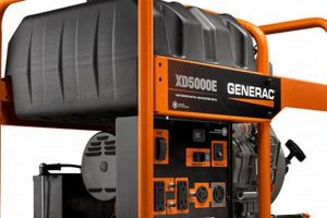
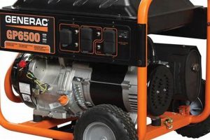
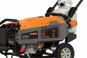
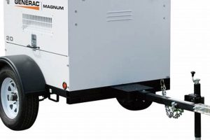
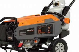
A visual representation of a portable power generation unit manufactured by Generac, illustrating the arrangement and interconnection of its components, serves as a crucial reference for maintenance, troubleshooting, and repairs. For example, such a representation might depict the engine, alternator, fuel system, control panel, and other constituent elements, clearly labeled and positioned relative to one another. This type of resource allows users to identify specific parts, understand their function within the overall system, and locate them physically on the machine.
Access to this type of visual resource is invaluable for both professionals and owners. It empowers users to perform routine maintenance, diagnose malfunctions effectively, and order replacement parts with accuracy. Historically, service manuals provided this information; however, digital accessibility has expanded the availability and ease of use of these resources. This facilitates quicker repairs, minimizes downtime, and can contribute to the extended operational lifespan of the equipment.
Understanding the function and location of individual components within a portable power generation system is foundational for proper operation and maintenance. The following sections delve deeper into specific systems, common troubleshooting scenarios, and recommended maintenance practices.
Tips for Utilizing Generac Portable Generator Diagrams
Effective use of component diagrams is crucial for successful maintenance and repair of portable power generation equipment. The following tips offer guidance on maximizing the benefits of these resources.
Tip 1: Locate the Correct Diagram. Ensure the diagram corresponds precisely to the specific model and version of the generator. Using an incorrect diagram can lead to misidentification of components and incorrect procedures.
Tip 2: Familiarize With the Legend. Diagrams often employ symbols and abbreviations. Studying the legend allows for accurate interpretation of the information presented.
Tip 3: Use the Diagram During Disassembly. Referencing the diagram while taking the unit apart helps maintain organization and ensures correct reassembly.
Tip 4: Cross-Reference with the Service Manual. While the diagram offers a visual representation, the service manual provides detailed instructions. Using both resources in conjunction delivers comprehensive guidance.
Tip 5: Pay Attention to Part Numbers. Diagrams often include part numbers, simplifying the ordering of replacement components.
Tip 6: Keep the Diagram Clean and Accessible. Protect the diagram from damage and store it in a convenient location for easy reference.
Tip 7: Utilize Digital Versions. Digital diagrams offer advantages such as searchability and zoom functionality, enhancing their usability.
Adherence to these practices improves efficiency in maintenance and troubleshooting, reduces the risk of errors, and contributes to the longevity of the equipment.
By understanding the layout and function of individual components, owners can maintain their equipment proactively and address issues effectively.
1. Visual Representation
Visual representation forms the core of a Generac portable generator parts diagram. A clear, detailed image provides the foundation for understanding the generator’s structure and the interrelationships of its components. This visual clarity is crucial for effective troubleshooting, maintenance, and repair. For instance, a diagram might illustrate the fuel system’s componentsfuel tank, fuel lines, fuel pump, and carburetorand their connections, enabling users to trace fuel flow and identify potential blockage points. Without a visual representation, isolating the source of a fuel delivery problem becomes significantly more challenging.
Different types of visual representations offer varying levels of detail and serve distinct purposes. Exploded view diagrams depict components separated but positioned to illustrate their assembly relationships. Schematic diagrams utilize symbols to represent components and their electrical connections, simplifying complex wiring systems. Cutaway views offer internal perspectives of the generator, revealing the arrangement of internal parts. The choice of visual representation depends on the specific task; an exploded view assists reassembly after maintenance, while a schematic aids in diagnosing electrical issues. Using the appropriate visual representation improves efficiency and reduces the likelihood of errors during maintenance and repair.
Effective visual representations within a Generac portable generator parts diagram enhance comprehension and facilitate practical application of knowledge. Clarity and accuracy in these diagrams directly impact the success of troubleshooting and repair efforts. Challenges can arise when diagrams lack sufficient detail or when they fail to accurately represent the specific generator model. Therefore, sourcing diagrams from reputable sources and verifying model compatibility is crucial. Proficiency in interpreting these visual representations is essential for anyone undertaking maintenance or repair of a Generac portable generator, ultimately contributing to the safe and efficient operation of the equipment.
2. Component Identification
Component identification is inextricably linked to the effective utilization of a Generac portable generator parts diagram. The diagram serves as a roadmap, visually presenting the generator’s components and their spatial relationships. Accurate component identification, using the diagram as a reference, is essential for various tasks, including routine maintenance, troubleshooting, and repair. Without precise identification, even simple tasks like replacing a spark plug become significantly more complex. For example, correctly identifying the voltage regulator on the diagram is crucial before attempting any adjustments or replacements to avoid causing further damage.
Practical application of component identification knowledge arises in numerous scenarios. During troubleshooting, a user might observe a malfunctioning fuel gauge. Consulting the diagram allows isolation of the fuel level sensor, enabling targeted testing and replacement if necessary. Similarly, routine maintenance tasks, such as oil changes, require accurate identification of the oil drain plug and dipstick. Furthermore, ordering replacement parts relies heavily on component identification. The diagram typically includes part numbers, enabling precise ordering of the correct component, preventing costly and time-consuming errors. Consider a scenario where a faulty recoil starter requires replacement. Identifying the specific recoil starter assembly on the diagram, along with its associated part number, ensures the correct part is ordered for efficient repair.
Mastery of component identification, facilitated by a well-structured parts diagram, is fundamental to proper generator maintenance and repair. Challenges arise when diagrams lack clarity or detail, or when variations between generator models create ambiguity. Therefore, utilizing diagrams specific to the exact generator model is crucial. Accurate component identification, grounded in a thorough understanding of the parts diagram, streamlines maintenance, improves diagnostic accuracy, and promotes efficient repair, contributing to the overall reliability and longevity of the equipment.
3. Exploded Views
Exploded views within a Generac portable generator parts diagram offer a unique perspective, separating individual components while maintaining their relative positions and orientations. This disassembly visualization clarifies assembly relationships, crucial for understanding how parts fit together. Consider the generator’s engine; an exploded view would illustrate the spatial relationship between the cylinder head, cylinder block, piston, and connecting rod, facilitating comprehension of the engine’s internal structure and assembly sequence. This visual clarity simplifies complex assemblies, especially during maintenance or repair involving disassembly and reassembly.
Practical applications of exploded views are numerous. During a carburetor rebuild, an exploded view guides the technician in correctly positioning gaskets, jets, and other small components. Similarly, when replacing a fuel pump, the exploded view clarifies its mounting and connection points within the fuel system. This visual aid reduces errors during reassembly, a critical factor in ensuring proper generator function. Furthermore, exploded views assist in understanding the removal and installation sequence for specific components. For instance, removing the generator’s recoil starter might require removal of other parts first. The exploded view clarifies this dependency, guiding the user through the correct disassembly procedure.
Effective use of exploded views within a Generac portable generator parts diagram significantly improves maintenance and repair efficiency. Challenges may arise when diagrams lack sufficient detail or when variations between generator models lead to discrepancies. Sourcing diagrams specific to the precise generator model is essential for accurate guidance. Proficiency in interpreting exploded views, recognizing how individual components contribute to the larger assembly, underpins successful maintenance and repair outcomes, maximizing the generator’s operational lifespan.
4. Schematic Diagrams
Schematic diagrams within a Generac portable generator parts diagram provide a specialized visual representation of the electrical systems. Unlike pictorial representations, schematic diagrams utilize symbols to depict components and their interconnections, simplifying complex wiring configurations and facilitating circuit analysis. Understanding these diagrams is crucial for diagnosing electrical faults and performing repairs effectively.
- Component Representation:
Schematic diagrams employ standardized symbols to represent electrical components, such as resistors, capacitors, diodes, and transistors. These symbols, coupled with labels and identifiers, allow technicians to quickly identify and locate specific components within the generator’s electrical system. For example, a diode might be represented by an arrow with a bar, while a resistor is depicted as a zigzag line. This standardized representation streamlines troubleshooting by allowing technicians to trace the flow of current and identify potential points of failure.
- Circuit Analysis:
Schematic diagrams facilitate circuit analysis by clearly illustrating the electrical connections between components. This visual representation allows technicians to understand the intended flow of current and voltage within the system. For example, tracing the connections from the generator’s alternator through the voltage regulator and to the output receptacles allows technicians to pinpoint potential voltage drop issues. This analytical capability is essential for accurate diagnostics and effective repair strategies.
- Wiring Identification:
Schematic diagrams depict wire colors, gauges, and connectors, essential information for troubleshooting and repair. This level of detail allows technicians to identify specific wires within the generator’s wiring harness, trace their paths, and check for continuity or shorts. For instance, if the generator fails to start, the schematic diagram assists in tracing the ignition system wiring to identify potential breaks or loose connections. This accurate wiring information is critical for safe and effective repairs.
- Safety and Troubleshooting:
Understanding schematic diagrams allows for safer and more efficient troubleshooting. By visually tracing circuits, technicians can isolate potentially energized components before working on them, minimizing the risk of electrical shock. Furthermore, schematic diagrams provide a framework for systematic troubleshooting, guiding technicians through the diagnostic process and reducing the likelihood of overlooking critical components or connections. This systematic approach leads to faster and more accurate repairs, minimizing downtime and maximizing the generator’s operational reliability.
Proficiency in interpreting schematic diagrams is fundamental for effectively utilizing a Generac portable generator parts diagram for electrical system diagnostics and repairs. These diagrams provide a specialized visual language essential for understanding complex wiring configurations, tracing circuits, and identifying potential points of failure. Accurate interpretation of these diagrams is crucial for ensuring safe and efficient repairs, maximizing the generator’s operational lifespan, and minimizing downtime. Combining schematic interpretation with practical knowledge contributes to successful generator maintenance and troubleshooting.
5. Troubleshooting Aid
A Generac portable generator parts diagram functions as a crucial troubleshooting aid, providing a visual roadmap for diagnosing and resolving operational issues. The diagram’s depiction of individual components, their interconnections, and their placement within the unit enables systematic fault isolation. Consider a scenario where a generator fails to produce power. The diagram facilitates tracing the electrical path from the engine to the output receptacles, allowing identification of potential failure points such as a faulty circuit breaker, a disconnected wire, or a malfunctioning voltage regulator. Without the diagram, this diagnostic process becomes significantly more challenging and time-consuming.
Effective troubleshooting relies on correlating observed symptoms with potential underlying causes. A parts diagram aids this process by enabling users to visualize the system’s operation and pinpoint components likely responsible for observed malfunctions. For example, difficulty starting the generator might indicate a problem within the fuel system. The diagram allows users to locate and inspect components like the fuel tank, fuel lines, fuel filter, fuel pump, and carburetor, systematically eliminating potential sources of the issue. This targeted approach streamlines the troubleshooting process, minimizing downtime and facilitating efficient repairs. Furthermore, the diagram’s inclusion of part numbers facilitates accurate replacement part ordering, further expediting the repair process.
Proficiency in utilizing a Generac portable generator parts diagram as a troubleshooting tool significantly enhances diagnostic capabilities. Challenges arise when diagrams lack sufficient detail or when available diagrams do not precisely match the specific generator model. Accessing accurate, model-specific diagrams is essential for effective troubleshooting. Furthermore, understanding the generator’s operating principles, coupled with systematic troubleshooting methodologies, maximizes the diagram’s utility. This combined approach ensures accurate diagnoses, leading to efficient repairs and restoring the generator’s functionality swiftly and effectively.
6. Maintenance Guide
A maintenance guide, inextricably linked to a Generac portable generator parts diagram, provides the procedural framework for preventative upkeep and repair. The diagram visually represents the generator’s components, while the maintenance guide details the necessary procedures, specifying component locations referenced within the diagram. This synergy is crucial for effective maintenance. For example, the maintenance guide might specify an oil change interval and procedure, while the diagram identifies the oil drain plug and dipstick locations, facilitating accurate execution of the oil change procedure. Without this connection, maintenance tasks become significantly more challenging, increasing the risk of errors.
Practical application of the combined diagram and guide arises frequently. Consider a routine air filter replacement. The maintenance guide outlines the replacement procedure, including frequency and steps. The diagram pinpoints the air filter housing location, facilitating quick access and correct filter replacement. Similarly, performing valve clearance adjustments requires the maintenance guide’s procedural instructions alongside the diagram’s identification of valve locations and adjustment points. This integrated approach ensures adherence to manufacturer specifications, optimizing generator performance and longevity. Ignoring this connection risks improper maintenance, potentially leading to premature component failure and reduced operational lifespan.
Effective generator maintenance hinges on the symbiotic relationship between the maintenance guide and the parts diagram. Challenges may arise when documentation is incomplete, inaccurate, or unavailable for specific generator models. Accessing model-specific documentation is crucial for proper maintenance. Furthermore, understanding basic mechanical principles and safety procedures enhances the utility of these resources. This comprehensive approach empowers users to perform maintenance confidently and correctly, maximizing generator reliability and lifespan.
7. Part Number Reference
Part number references within a Generac portable generator parts diagram are essential for accurate component identification and acquisition. These alphanumeric codes, typically located adjacent to or within the component’s depiction on the diagram, serve as a unique identifier, eliminating ambiguity when ordering replacements. This precision is critical given the potential variations between seemingly similar components across different generator models or production years. Without accurate part numbers, acquiring the correct replacement part becomes a significantly more challenging and error-prone process, potentially leading to compatibility issues and operational failures.
- Accurate Ordering:
Part numbers provide the necessary specificity for accurate replacement part ordering. A diagram might illustrate multiple similar-looking bolts, but their respective part numbers differentiate their specific dimensions, thread pitch, or material composition. Ordering based solely on visual similarity could result in acquiring an incorrect bolt, potentially compromising the generator’s structural integrity or function. Using the correct part number ensures the acquisition of the appropriate replacement, avoiding compatibility issues and ensuring a proper fit.
- Inventory Management:
Part numbers play a crucial role in inventory management for maintenance providers and parts suppliers. These codes facilitate efficient stock control, allowing for accurate tracking of inventory levels and streamlined reordering processes. This efficiency minimizes delays in repairs due to part unavailability, contributing to faster turnaround times and reduced downtime for generator owners. Accurate inventory management based on part numbers translates to improved customer service and operational efficiency.
- Technical Documentation:
Part numbers serve as cross-referencing points within technical documentation, such as service manuals and troubleshooting guides. This interconnectedness allows technicians to quickly locate relevant information regarding a specific component, including installation instructions, maintenance procedures, and troubleshooting steps. This streamlined access to information improves diagnostic accuracy and repair efficiency, minimizing downtime and optimizing generator performance. The integration of part numbers within technical documentation creates a cohesive information ecosystem, empowering technicians with readily accessible and precise data.
- Version Control and Compatibility:
Part numbers reflect design revisions and component updates. When a component undergoes modification, its part number typically changes, ensuring clarity and preventing the installation of obsolete or incompatible parts. This version control system is critical for maintaining generator safety and performance. Utilizing the correct, updated part number guarantees compatibility with the specific generator model and its current configuration, minimizing the risk of operational issues or safety hazards.
Accurate part number referencing, facilitated by a comprehensive Generac portable generator parts diagram, underpins effective maintenance, repair, and inventory management practices. This precision minimizes errors, reduces downtime, and contributes to the generator’s long-term reliability and performance. The seamless integration of part numbers within the diagram and associated technical documentation streamlines the entire maintenance and repair process, ultimately benefiting both service providers and generator owners.
Frequently Asked Questions
This section addresses common inquiries regarding the utilization and interpretation of Generac portable generator parts diagrams.
Question 1: Where can one locate official Generac portable generator parts diagrams?
Official diagrams are typically found within the generator’s accompanying owner’s manual or service manual. Generac’s official website also provides access to documentation, often organized by model number. Authorized dealers and service centers represent additional potential sources.
Question 2: What information is typically included within a parts diagram?
Diagrams usually include individual component illustrations, part numbers, and their relative locations within the generator assembly. Exploded views and schematic diagrams might also be present, offering further clarity regarding assembly relationships and electrical systems.
Question 3: How does one interpret the symbols and abbreviations used within a parts diagram?
A legend, typically included within the diagram or accompanying documentation, explains the meaning of symbols and abbreviations. Consulting this legend is essential for accurate interpretation.
Question 4: Can parts diagrams assist in troubleshooting generator malfunctions?
Absolutely. Diagrams facilitate systematic fault isolation by enabling users to visualize component locations and interconnections. This visual aid assists in tracing potential failure points, streamlining the diagnostic process.
Question 5: Are parts diagrams specific to individual generator models?
Yes. Using a diagram specific to the exact generator model is crucial. Variations exist between models, and utilizing an incorrect diagram can lead to misidentification of components and incorrect procedures.
Question 6: How does one utilize a parts diagram when ordering replacement components?
The diagram typically includes part numbers adjacent to each component. Providing this part number when ordering ensures receipt of the correct replacement, eliminating compatibility issues.
Accurate interpretation and application of information presented within a Generac portable generator parts diagram is essential for effective maintenance, troubleshooting, and repair. Careful attention to detail, coupled with model-specific documentation, ensures successful outcomes.
The next section delves into practical examples of common maintenance procedures facilitated by effective diagram utilization.
Conclusion
Generac portable generator parts diagrams provide an essential visual resource for understanding, maintaining, and repairing these complex machines. From component identification and exploded views to schematic diagrams and part number references, these diagrams offer invaluable support for both routine maintenance and complex troubleshooting. Effective utilization hinges on accessing model-specific diagrams and correctly interpreting the presented information. This understanding empowers users to perform maintenance tasks confidently, diagnose malfunctions accurately, and order replacement parts with precision, contributing significantly to the generator’s operational longevity and reliability.
Investing time in understanding these diagrams represents an investment in the generator’s lifespan. Proactive engagement with these resources empowers users to address potential issues effectively, minimizing downtime and maximizing the return on investment. Proper utilization of Generac portable generator parts diagrams ensures these machines remain reliable power sources when needed most.

